6 operating status messages and led displays – NORD Drivesystems BU0240 User Manual
Page 35
6 Status messages
BU 0240 GB
35
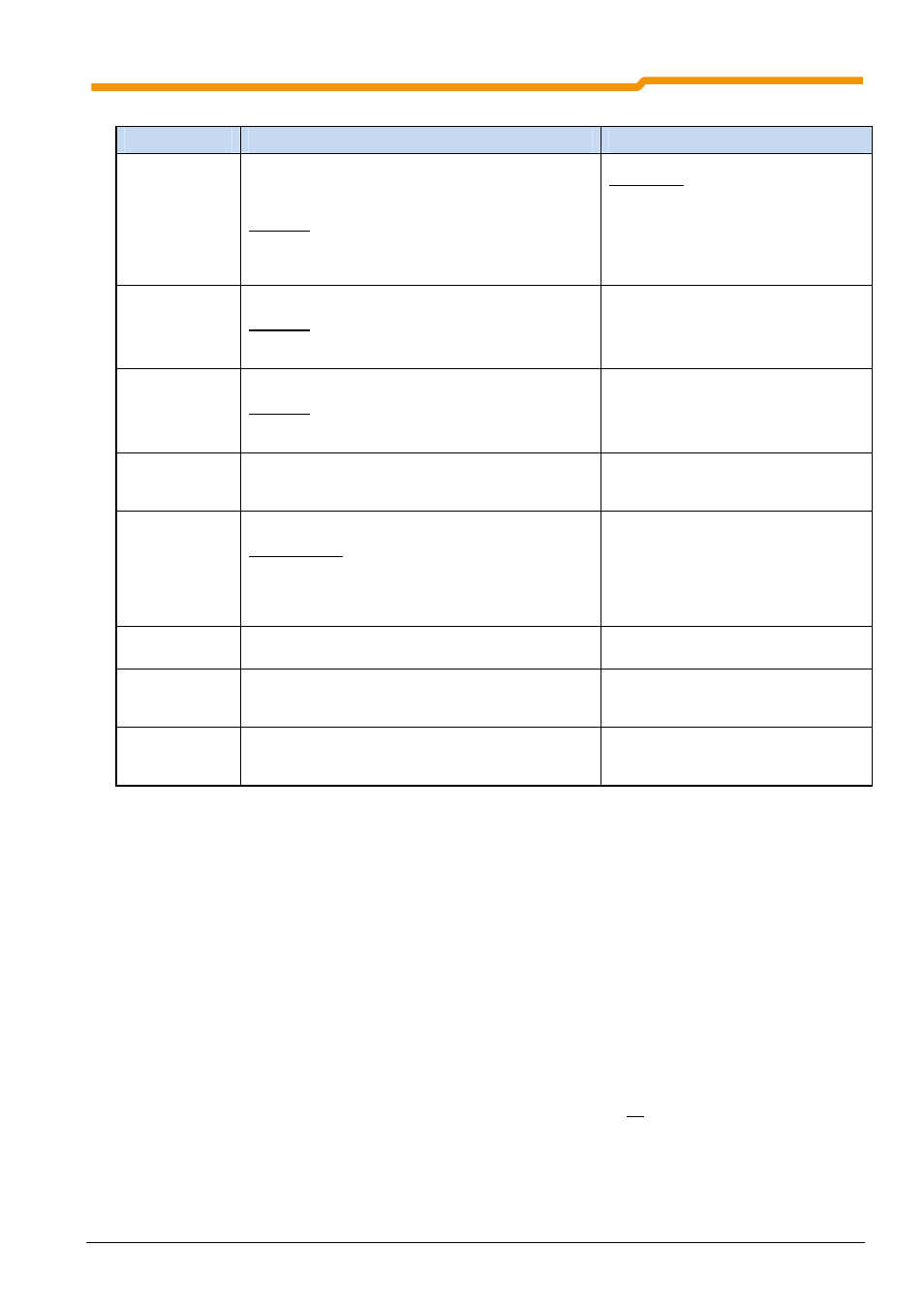
Parameter list - inverter information (selection)
Parameter
Description
Settings / functions (selection)
P700
Current
operating status
Display of current messages for the actual operating
status of the frequency inverter such as errors,
warnings or the cause of a switch-on block.
Selection:
Current error (P700, Array -01)
Current warning (P700, Array -02)
Reason for switch-on block (P700, Array -03)
Error group:
1 / 2 = Overtemperature of inverter / motor
3 / 4 = Overcurrent error
5 = Overvoltage error
16 = Motor phase monitoring
19…= Parameter identification error
P701
Last error
Displays the last 5 frequency inverter errors.
Selection:
Last error (P701, Array -01)
Second to last error (P701, Array -02)
See P700
P707
Software version
Displays the firmware version / Inverter revision
Selection:
Software version (P707, Array -01)
Revision (P707, Array -02)
P708
Digital input
status
Shows the switching status of the digital inputs.
Bit 0 = DIN 1
Bit 1 = DIN 2
…
P709
Analog input
voltage
Displays the measured analog input value.
Input selection:
Poti P1 (P400, Array -01)
Poti P2 (P400, Array -02)
DIN 2 (P400, Array -06)
DIN 3 (P400, Array -07)
P719
Actual current
Displays the actual output current.
P740
Process data
Bus In
Displays the actual control word and the setpoints.
[-01] = STW (Source P509)
[-02…-04] SW 1…3 (Source P510[-01]
[-11…-13] SW 1…3 (Source P510[-02]
P749
DIP switch status
Displays the current DIP switch setting.
Bit 0 = DIP switch 1
Bit 1 = DIP switch 2
…
6 Operating status messages and LED displays
The frequency inverter generates operating status messages. These messages (warnings, errors, switching
statuses, measurement data) can be displayed with parameterisation tools (e.g. ParameterBox) (Parameter
group P7xx).
To a limited extent, the messages are also indicated via the diagnostic and status LEDs.
Error messages
Errors cause the frequency inverters to switch off, in order to prevent a device fault.
The following options are available to reset a fault (acknowledge):
1. Switching the mains off and on again,
2. By an appropriately programmed digital input (P420 = Function 12),
3. By switching of the “enable” on the frequency inverter to Low (if no digital input is programmed for
acknowledgement),
4. By Bus acknowledgement or
5. by P506, the automatic error acknowledgement.
An error message can only be acknowledged if its direct cause is no longer present.