Commissioning examples – NORD Drivesystems BU0240 User Manual
Page 24
NORDAC SK 200E Manual
24
BU
0240
GB
4.1.3
Commissioning examples
4.1.3.1 Test
operation
A SK 200E series frequency inverter which is to be used to control a 4-pole motor of the same power can be
operated without any aids to testing purposes.
The only condition for this is the correct connection of the mains and motor cables and the supply of a 24V
DC control voltage to the inverter (See Section 4.1.1).
The PTC input must be bypassed, if a motor with PTC is not available.
Configuration
For test operation the DIP switches 1 to 5 of the frequency inverter must be set to the "OFF" position and
the digital input DIN1 (terminal 21) must be hard-wired to the 24V control voltage.
Control
Enabling is carried out as soon as the inverter's own setpoint potentiometer (Potentiometer P1, Section ) is
moved from the 0% position.
The setpoint can be adjusted to the requirements by further continuous adjustment of the potentiometer.
Resetting the setpoint to 0% sets the frequency inverter into "Standby" status.
Stepped adjustment of the ramp times within defined limits is also possible with the aid of potentiometer P2.
NOTE
This setting method is not suitable for the implementation of a so-called "automatic start with
mains".
In order to use this function, it is essential that parameter (P428) "Automatic Start" is set to the
function "ON". Adjustment of parameters is possible with the aid of a ParameterBox
(SK xxx-3H) or with the NordCon software (Windows PC and adapter cable required).
4.1.3.2 Normal
operation
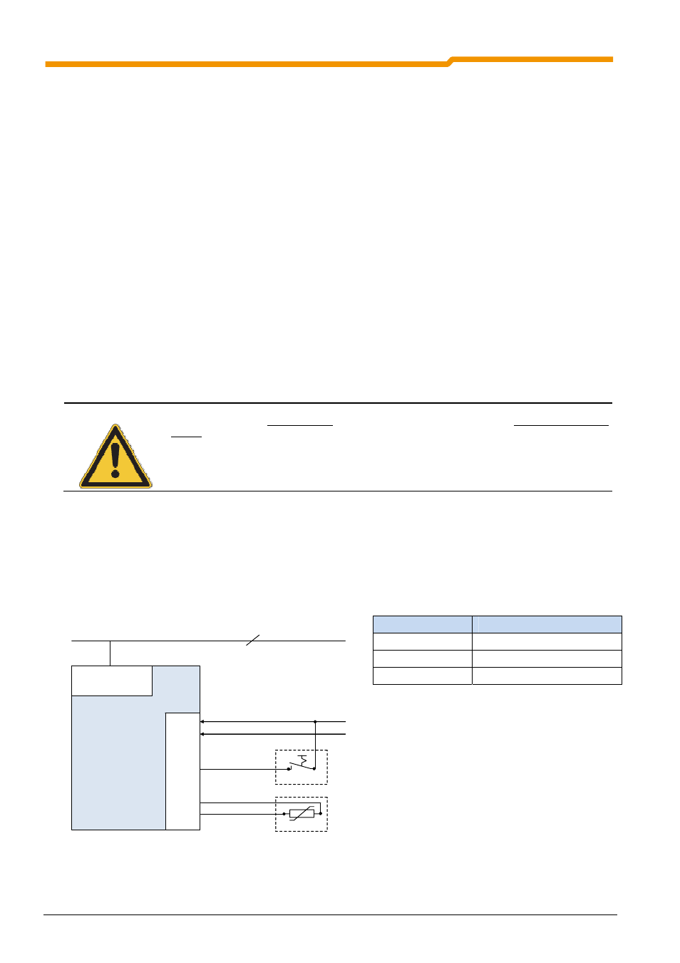
Minimal configuration without options
The simplest version of normal operation is implemented by the integration of a switch to enable the
controller instead of the hard wiring of the digital input 1 to 24V.
Parameter (P428) must be changed if an automatic startup with "Mains On" is required.
Function
Setting
Setpoint
Integrated potentiometer P1
Frequency ramp
Integrated potentiometer P2
Controller enable
External switch S1
Frequency inverter
SK 2x5E-...
Contro
l t
erm
in
al bar
44
40
.
.
21
22
.
38
39
L1 - L2/N - L3
115/230/400V
24V=
GND
1/3~ 115/230/400V + PE
Switch S1
Motor PTC