Î attention – NORD Drivesystems B1904 User Manual
Page 17
Operating and Installation Instructions FDB (Getriebebau NORD)
Version 08.2011
Page
17
of 23
The rotor is fixed to the motor shaft and revolves with the motor shaft and brakes the shaft when
power is removed from the brake:
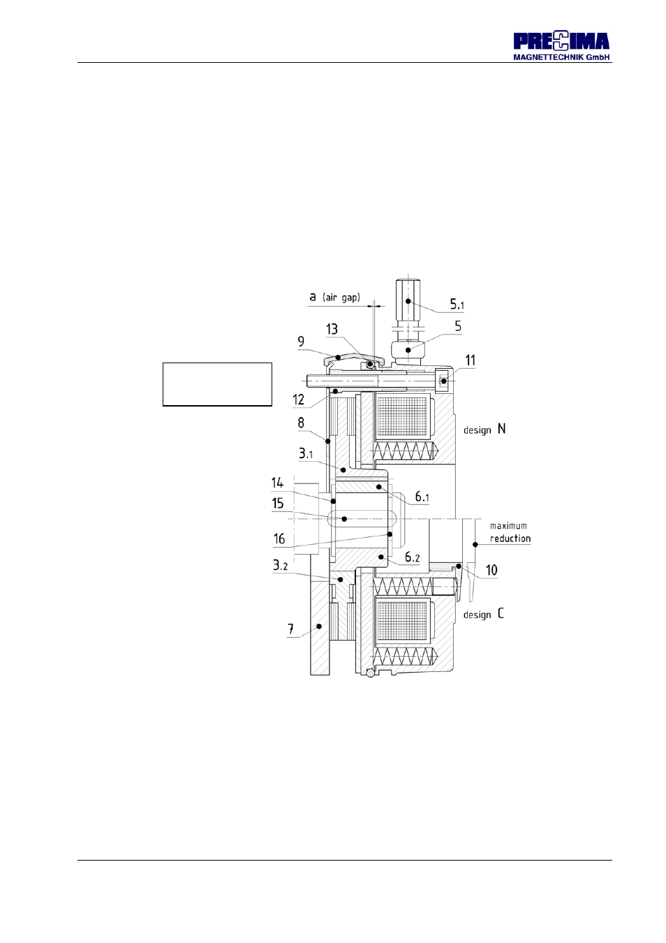
- Insert the first circlip (item 14) into the rear radial groove of the shaft
- Insert the feather key (item 15) into the axial groove of the shaft
- Push the toothed hub (item 6.1) or the hexagon hub (item 6.2) onto the shaft and over the
feather key
- Axially fix the hub by inserting the second circlip (item 16) into the front radial groove of the
shaft
- Push the rotor (item 3.1 or 3.2) onto the hub The rotor must be able to move axially on the
hub.
ÎAttention!
Pay attention to the smooth running of the rotor/hub pair!
4.1.4 Brake
(illustration 4.1)
The brake is attached to the flange or to the motor flange (if this is the counter-friction surface or
if a friction plate is used). The important adjustments need to be made for safe operation of the
brake, if necessary, the brake will be supplemented by additional component parts:
- Fit the brake onto the rotor, insert the fastening screws (item 11) until hollow screws (item
12
) rest on the counter-friction surface.
- Check the size of air gap a in order to keep the nominal value (+ tolerance) by means of a
feeler gauge at three positions on the circumference and, if necessary, correct it by turning
the hollow screws (for values of nominal air gap and tolerance: see 3.2.2.4).
Î
How to proceed in order to correct the air gap refer to 5.1.3.1.
Illustration 4.1:
Brake assembly
(sectional view)