NORD Drivesystems B1904 User Manual
Page 12
Operating and Installation Instructions FDB (Getriebebau NORD)
Version 08.2011
Page
12
of 23
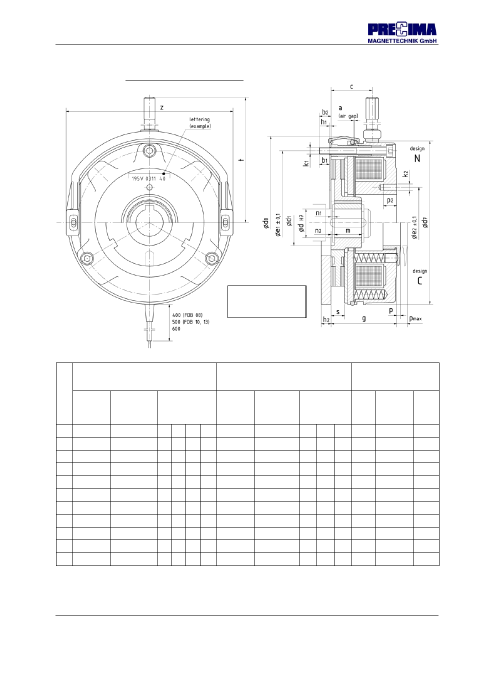
3.2.2.3 Dimensions, masses, attachment (illustration 3.2)
Siz
e
Hub dimensions
[mm]
General brake dimensions
[mm]
Dimensions of
tapped bores
[mm]
- only design N -
Hexagon
hub
Ød
H7
Toothed
hub
Ød
H7
Mounting
dimensions
Brake
without /
with dust
guard ring
Brake in new
condition
Brakes with
manual
release
Hole
circle
Øe1
±0,1
(Bore
qty.)
x thread-
nom.-Ø
thread
depth
d d
d
1
m n
1
n
2
d
7
/ d
8
g / h
1
/ h
2
c
t z e
2
k
2
p
2
08
11/14/15 11/14*/15* 20
18
1,5 0,5
85 / 89
40 / 1,5 / 6 22 100
89
34
(3 x) M4
8
10
15/19/20*
14/15
25 20 2,5
1 105 / 109
48 / 1,5 / 7 21 110
111
40
(3 x) M5
12
13
15/20/25
15/20
33 20 3,5 1,5 130 / 135
53 / 1,5 / 9 33 130
132
54
(3 x) M6
12
15
20/25/30
20/25
42 25 3
2 150 / 155
60 / 1,5 / 9 38 140
151
65
(3 x) M6
12
17
-
25/30/35*
- 30 3
-
170 / 175
70 / 2 / 11
42 165
172
75
(3 x) M8
15
20
-
30/35/40
- 30 3
-
195 / 201
80 / 2 / 11
48 186
196
85
(3 x) M8
15
23
-
35/40/45
- 35 4
-
225 / 231
90 / 2 / 11
51 200
224
95
(3 x) M8
15
26
-
40/45/50/55* - 40 4
-
258 / 264
99 / 2 / 11
57 285
258
110 (6 x) M10
25
30
-
50/55/60/65* - 50 4
-
306 / 312 105/ 2 /12,5 59 310
304
138 (6 x) M10
25
40
-
65/70/75/80* - 70 4
-
400 / 408 120,6 / 18** 69 415
403
180 (6 x) M12
43***
Standard feather key groove of the hub as per DIN 6885/1-JS9
* deviating feather key groove as per DIN 6885/3-JS9 // ** no option Friction plate; dimension h
2
(Flange)
*** seperate inner pole: 8 mm without thread (through-hole)
Illustration 3.2:
Main dimensions of
the brake
a
(air gap) and s (rotor size): see
3.2.2.4