Alarm output (d502, d503, and d505) – FUTEK IPM500 (D500) Digital Display User Manual
Page 9
Revision 04
Alarm Output:
For meter models with alarm output installed it is possible to set alarms. There are two alarms that
can be programmed to activate once the programmed set-points are surpassed. The alarms are active
when the LEDs on the top corners of the display are illuminated. With this alarm option the user must
enter the setpoint at which the alarm will be activated, the type of alarm it will be, as well as the
characteristics of the alarm. The alarms can also be hooked up as an output in order to activate
external devices. The setup for this function is below.
Setup:
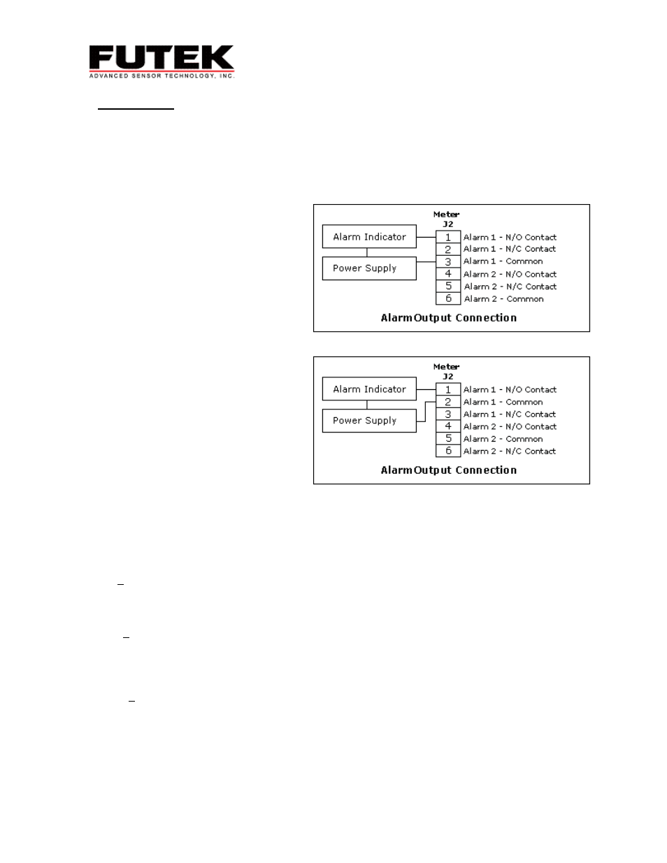
The alarm output setup is shown to
the right. An example of an alarm
indicator is a noise alarm that will
sound once the alarm is activated
and the normally open relay is
closed. If you are using alarm 1 it is
only necessary to hook up alarm 1.
There is no internal power source for
the alarm relay so it is necessary to
connect a power source in the
connection. First, decide if you would
like to use a normally open (N/O)
switch or a normally closed (N/C)
switch. Once you have made your
decision use the corresponding pin,
connect one wire to the N/O or the
N/C switch and the alarm indicator
(sound alarm). Connect the other
wire from your alarm indicator to the
external power source. Finally
connect a wire from the alarm
ground (Common) to the power
source. You are now ready to
configure the alarm.
Alarm Output for Serial # 0 - 227233
Alarm Output for Serial # 227234 and Up
Configuration:
1. Apply Power
2. Press the MENU button until ALSEt appears. Press the PEAK button.
3. Here you are to enter the alarm operation setup. A five-digit number will appear on the display,
‘00000’. What each digit represents is listed below. Once you have made your decisions regarding
the setup of the alarm enter those numbers in this menu and press MENU.
00000 – Relay status when alarm is active,
0 – Relay 1 on, Relay 2 on
1 – Relay 1 off, Relay 2 on
2 – Relay 1 on, Relay 2 off
3 – Relay 1 off, Relay 2 off
00000 – Alarm latching or non-latching status (weather or not the alarm will turn off when the
displayed value returns to normal ranges)
0 – AL1, AL2 non-latch
1 – AL1 latch, AL2 non-latch
2 – Al1 non-latch, AL2 latch
3 – AL1, AL2 latch
00000 – alarm status (this determines if the alarm will be activated once the displayed value is either
higher (active high) or lower (active low) then the set setpoint)
0 – AL1 active high
AL1 active high
1 – AL1 – active low
AL2 – active high
2 – AL1 – disabled
AL2 active high
8