Setup/connections – FUTEK IPM500 (D500) Digital Display User Manual
Page 3
Revision 04
Setup/Connections:
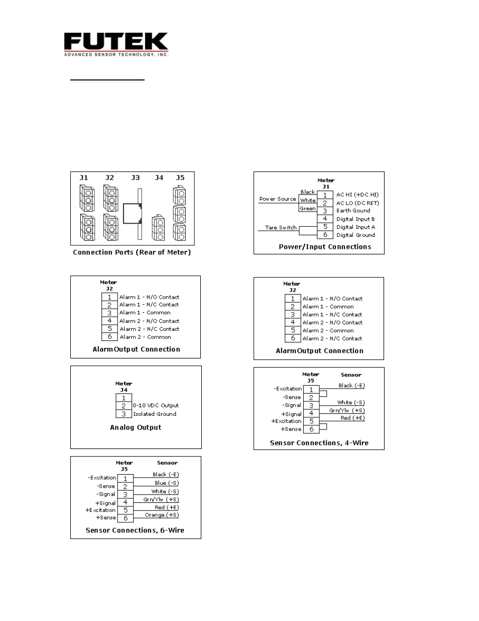
Correct setup is essential to the operation of your sensor and meter. The back of the IPM500 is shown in
the drawings below. Locate the wiring code for your individual sensor and connect accordingly. For a
four wire load cell it is necessary to jump the +/- Excitation and +/-Sense (pictured).
The pictures below show the connections for the power, a 4-wire sensor, a 6-wire sensor, the analog
output and the alarm output. The center port (J3) is the serial communications port for those meters with
RS232 output option. Note: Not all meters will have all of these options. For example, meters without
alarms will not have the J2 ports. The power controls are found on the back left of the meter. The blue or
green screw connector indicates that your meter requires AC voltage. If your screw connector is black or
brown your meter requires DC voltage. IF YOU ARE USING DC VOLTAGE DO NOT PLUG THE METER INTO
AN AC WALL SOCKET. EVEN IF YOUR METER COMES WITH A POWER CORD IT IS NOT TO BE USED.
Alarm Output for Serial # 0 - 227233
Alarm Output for Serial # 227234 and Up
2
0-20 mA Output