Outputs – Dwyer 16A User Manual
Page 6
Page 6
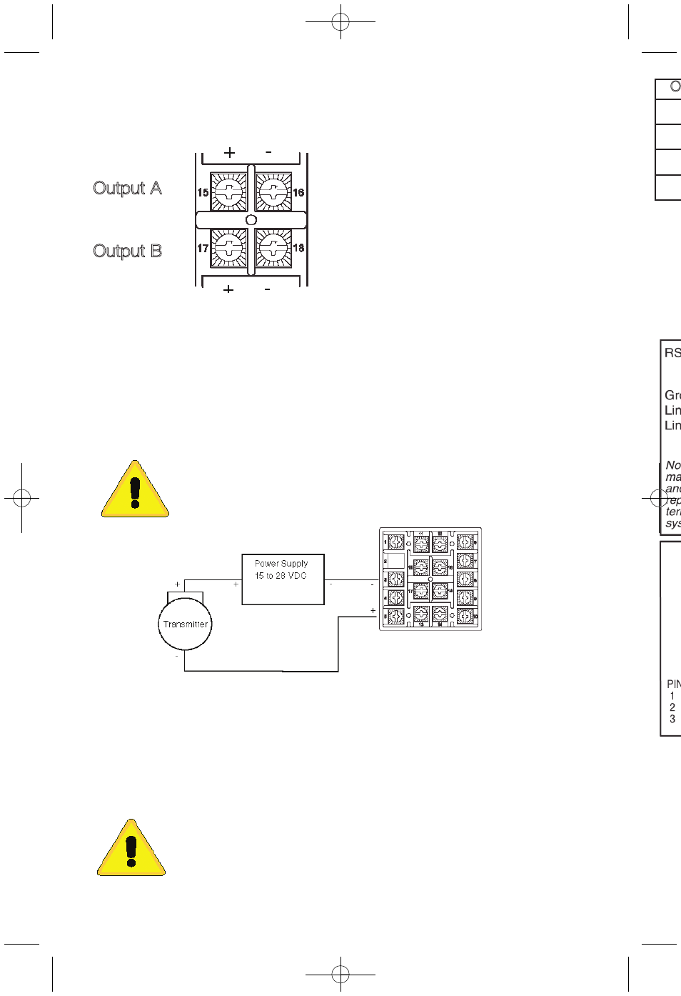
OUTPUTS
(Rear View showing center block of wiring terminals.)
Output A
Output B
For AC SSR or relay type outputs
(Output Codes 1 or 3), 15 & 16, and 17
& 18 are normally open. See Rating
Label for details.
For Pulsed DC, Current, or DC SSR
ouputs (Output codes 2, 4, or 8), 15 &
17 are positive, 16 & 18 are negative.
Note: Factory default assigns Output A to Set Point 1 and Output B to Set Point 2.
If necessary, these realtionships may be reversed. See
SP 10 in the Secure Menu.
Wiring power and ouputs as shown above. Two-wire transmitters wire as shown
below. View is of instrument as seen from the rear to show wiring terminals.
For three or four-wire transmitters, follow the wiring instructions provided with your
transmitter.
CAUTION: DO NOT WIRE THE 24 VOLT POWER SUPPLY
ACROSS THE INPUT OF THE CONTROL. DAMAGE TO THE
CONTROL INPUT CIRCUITRY WILL OCCUR.
Wiring for 4 to 20mA Transmitter Inputs
Options are described on Page 3. Detailed option programming and operation
starts on Page 13. Wire power and outputs as shown on Pages 5 and 6. Wiring
for options is shown opposite. All wiring shown above is CLASS 2. Shielded twist-
ed pair is required for Options 992 and 994. Shielded cable is required for Options
993 and 995.
Wiring for Optional Inputs and Outputs
CAUTION: DO NOT RUN SIGNAL WIRING IN THE SAME CON-
DUIT OR CHASE AS THE POWER WIRING. ERRATIC OPERATION
OR DAMAGE TO THE CONTROL CIRCUITRY WILL OCCUR.
O
PV1 P
Curre
PV2 P
Voltag
992, 9
Comm
993, 9
Comm
949-1265:Layout 1 1/25/11 10:22 AM Page 6