Bwls series – Blue Angel Pumps BWLS200 User Manual
Page 3
Operation
Never run the
pump dry. Running
pump without water may cause seal
damage. Fill the pump with water
before starting.
PRIMING THE PUMP
After pump installation is complete,
the pump must be primed. Remove the
pipe plug in the discharge piping and
fill the pump and suction pipe with
clean water. Turn power to pump on. If
the pump does not pump water in 10
minutes, turn off the pump and refill
with clean water.
If the pump does not operate after
repeated attempts, check the follow-
ing:
1. Vertical distance of pump to water
level must not be over 25 feet.
2. Suction piping must be air tight.
3. Be sure valve(s) are open if used in
discharge or suction piping.
Never run the
pump with a
closed or clogged discharge. The water
inside the pump could boil and damage
the pump.
Maintenance
Maintain adequate ventilation for the
pump motor. The motor bearings are
permanently lubricated at the factory.
Additional lubrication is not required.
3
Operating Instructions and Parts Manual
Dug Well, Cistern, Lake And
Spring Installation
1. Install a foot valve on the inlet pipe
and lower into the water.
Locate foot valve
no closer than 2
feet from the bottom of the water
source so sand or sediment is not
drawn into the system.
NOTE: When a lake is used for the
water supply, make sure the suction
pipe is deep enough to be submerged
at all times. Slope the pipe upward
toward the pump to eliminate trap-
ping air. The pipe must be removed
during winter months or protected
against freezing.
Protect the pipe
from damage by
swimmers and boaters.
Electrical Connections
Connect the pump to a separate elec-
trical circuit with a dedicated circuit
breaker. Refer to the electrical specifi-
cations in wiring chart for recommend-
ed circuit breaker and wire size.
Install and maintain wiring for this
pump in accordance with the National
Electrical code and all applicable local
electrical codes.
The motor must be grounded by con-
necting a copper conductor to the
grounding screw provided within the
wiring compartment.
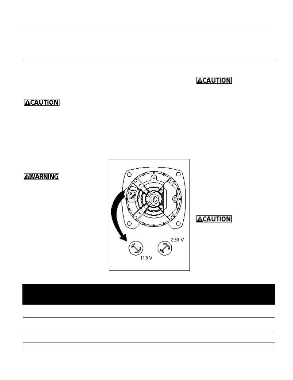
The voltage of power supply must
match the voltage of the pump. The
BWLS75, BWLS100 and BWLS150 have
dual voltage motors preset at the fac-
tory to 230 volts. The motors can be
converted to 115 volts by turning the
voltage selector to the desired voltage
(See Figure 5). Use a needle nose pliers
to pull the selector out approximately
1/4”, rotate and then reinsert in correct
position. The BWLS200 cannot be
converted; the motor is 230 volts
only.
BWLS Series
Figure 5 - Voltage Selector
BWLS75
3/4
115
13.5
20
12
12
10
10
230
7.0
15
14
14
12
12
BWLS100
1
115
14.8
20
12
12
10
10
230
7.4
15
14
14
12
12
BWLS150
1-1/2
115
17.0
30
10
10
8
8
230
8.5
15
14
14
12
12
BWLS200
2
230
12.0
15
14
14
12
12
Distance in Feet From Motor to Supply
Max.
Fuse
0
51
101
201
Load
Rating
50
100
200
300
Model
HP
Volts
Amps
Amps
(AWG Wire Size)
WIRING CHART - RECOMMENDED WIRE AND FUSE SIZES
www.blueangelpumps.com