Installation, Operation – Blue Angel Pumps BWST50 User Manual
Page 2
Installation
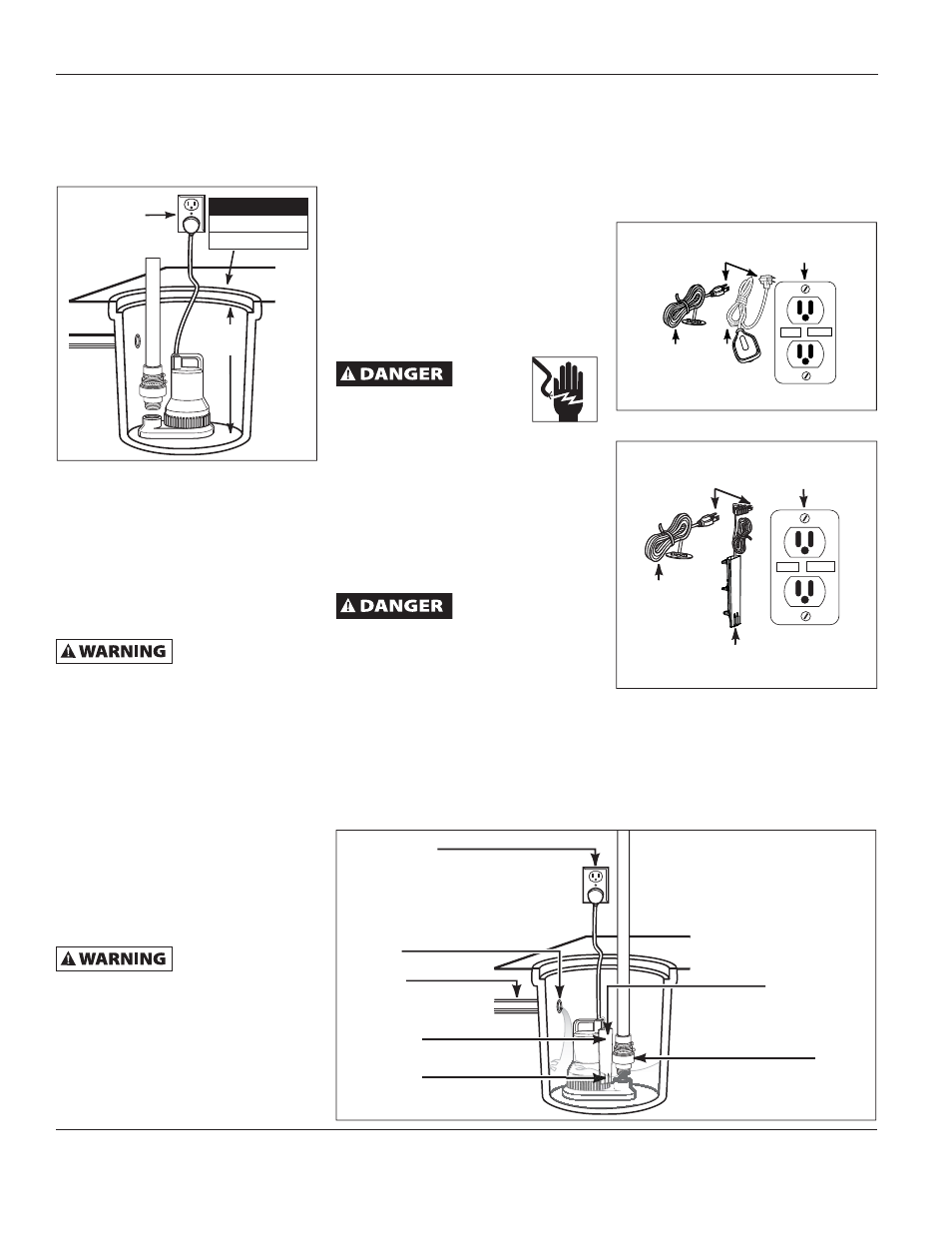
1. Install pump in a sump pit with
minimum size as shown in Figure 2.
Construct sump pit of tile, concrete,
steel or plastic.
2. The unit should be located and
rest on a solid, level foundation.
Do not place pump directly on clay,
earth, gravel or sandy surface. These
surfaces contain small stones, gravel,
sand, etc. that may clog or damage
the pump and cause pump failure.
Flood risk. If fl exible
discharge hose is
used, make sure pump is secured in
sump pit to prevent movement. Failure
to secure pump could allow pump
movement and switch interference
and prevent pump from starting or
stopping.
3. Thread check valve (Blue Angel
offers Model 66005-BLA) into pump
body carefully to avoid stripping
or cross threading. Do not use pipe
joint sealant.
4. Connect 1-1/2 inch rigid pipe to
rubber boot on check valve. Reverse
boot for 1-1/4 inch diameter pipe.
Tighten hose clamps.
Support pump and
piping
when
assembling and after installation.
Failure to do so could cause piping to
break, pump to fail, etc. which could
result in property damage and/or
personal injury.
5. Protect electrical cord from
sharp object, hot surfaces, oil
and chemicals. Avoid kinking the
2
Operating Instructions and Parts Manual
www.blueangelpumps.com
24 in.
Min.
Grounded
Outlet
Figure 2
cord and replace damaged cords
immediately.
IMPORTANT: Make sure there is
adequate room for the switch to
operate.
6. A sump pit cover must be installed
to prevent debris from clogging or
damaging the pump.
7. FOR BWSCAP MODELS ONLY:
Position pump switch AWAY from
the inlet so switch is clear from
incoming water (See Figure 3).
Operation
Always
disconnect
the power source before
attempting to install, service,
relocate or maintain the
pump. Never touch sump pump, pump
motor, water or discharge piping when
pump is connected to electrical power.
Never handle a pump or pump motor
with wet hands or when standing on
wet or damp surface or in water. Fatal
electrical shock could occur.
1. A ground fault circuit interrupter
(GFCI) is required.
Risk of electrical
shock! This pump is
supplied with a grounding conductor
and grounding type attachment plug.
Use a grounded receptacle to reduce the
risk of fatal electrical shock. Never cut
off the round grounding prong. Cutting
the cord or plug will void the warranty
and make the pump inoperable.
2. This pump is only for use on 120 Volt
(single-phase), 60 hz, 15 amp service
and is equipped with a 3-conductor
cord and 3-prong, grounding type
Min. Diameter
BWSF
11 in.
BWST
14 in.
plug. Insert the float switch cord
plug directly into a 120 volt outlet.
3. Insert the pump power cord plug
directly into the back of the float
switch cord plug or solid-state water
sensor cord plug (See Figures 4a and
4b).
4. Fill sump with water. The pump will
start automatically when the water
has filled the sump to the cut-in
level. The pump will stop when the
water reaches the cut-out level. See
Grounded Outlet
Incoming Water
Inlet Pipe
ON @ 8 inches
OFF @ 3 inches
Switch
Check Valve
Figure 3
Grounding
Blade
Grounded
Outlet
Power
Cord
Switch
Cord
TEST
RESET
Figure 4a
Grounding
Blade
Grounded
Outlet
Power
Cord
Switch
Cord
TEST
RESET
Figure 4b