Badger Meter M-Series M1000 User Manual
Page 26
Inputs/Outputs
Digital Outputs
(continued)
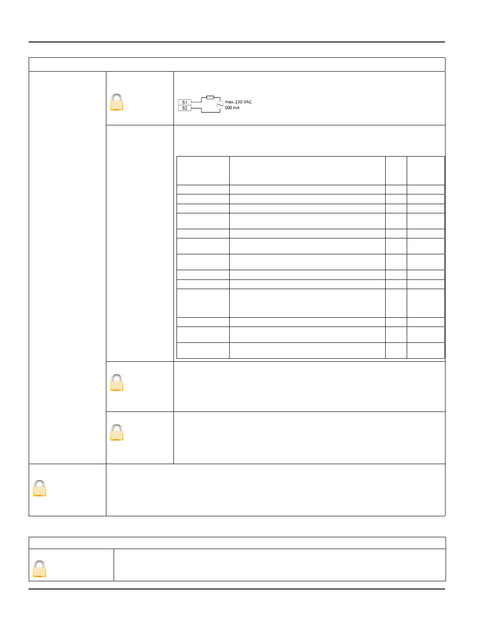
Out 1 Function
Out 2 Function
S
(continued)
Solid-State Relay
The solid-state relay is functionally linked with Output 2 . See the table below .
The following functions can be selected for the Outputs 1 to 2 as well as for
the solid-state relay . The solid-state relay function is linked with the function of
Output 2 .
Function
Meaning
Out1
Out2 /
Solid-
State
Relay
Off
Digital output is switched off .
X
X
Test
Used only for the Verification Device .
X
X
Comparator
TBD
X
X
Empty Pipe
Error
Indicates when a pipe is empty .
X
X
Error Alarm
Indicates a meter error condition .
X
X
Forward
Pulses
Generates pulses during forward flow
conditions .
X
X
Reverse Pulses
Generates pulses during reverse flow
conditions .
X
X
Direction
Indicates current flow direction .
X
X
Loopback
Shows the status of the digital input .
X
X
Min ./Max .
Alarm
Establishes, as a percentage of full scale flow,
the threshold at which the output alarm will
be activated . Flow rates below or above the
threshold will activate the output alarm .
X
X
Frequency
TBD
X
X
Rotary
Encoder
TBD
X
X
Preset
Indicates when a preset batch amount has
been realized .
X
X
Out Type 1
S
This parameter lets you set the output switch to normally open or normally
closed . If normally open is selected, the output switch is open (no current) when
the output is inactive, and closed (current flows) when the output is active .
If normally closed is selected, the output switch is closed (current flows) when
the output is inactive, and open (no current) when the output is active .
Out Type 2
S
This parameter lets you set the output switch to normally open or normally
closed . If normally open is selected, the output switch is open (no current) when
the output is inactive, and closed (current flows) when the output is active .
If normally closed is selected, the output switch is closed (current flows) when
the output is inactive, and open (no current) when the output is active .
Simulation
S
Flow Simulation provides analog and digital output simulation based on a percentage of the full
scale flow in cases where no real flow is occurring . The range of simulation is –100…100% in steps
of 10% of the full scale flow . This function still remains active once you have left the menu . It is
necessary to set it to OFF to deactivate it . If the simulation is still active, the letter “S” will be displayed
in the measuring mode .
Totals Menu
Totals
Clear T2
U
The unidirectional Totalizer T2 is reset within the menu manager .
M1000 main menu programming options
Page 26
July 2014
MAG-UM-00379-EN-02