Badger Meter MR Transmitter User Manual
Page 9
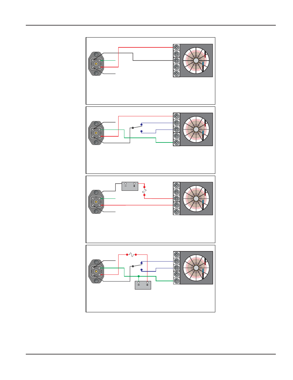
Schematic 4: 0…5 Vdc or 0…10 Vdc connection using
targets external power supply.
4
2
1
3
Black
Green
White
Red
Fuse: 0.05 A Fast
Excitation
Voltage
0-10 VDC Input
Ground
0-5 VDC Input
Example:
Chart Recorder
Schematic 3: 4…20 mA connection using targets
external power supply.
4
2
1
3
Black
Green
White
Red
Fuse: 0.05 A Fast
Excitation
Voltage
4-20 mA Input (+)
4-20 mA Input (-)
Example:
Chart Recorder
Schematic 2: 0…5 Vdc or 0…10 Vdc connection using
targets power supply.
4
2
1
3
Black
Green
White
Red
Sensor Excitation
0-10 VDC Input
Ground
0-5 VDC Input
Example:
Chart Recorder
Schematic 1: 4…20 mA connection using targets
power supply.
4
2
1
3
Black
Green
White
Red
External DC
Sensor Excitation
4-20 mA Input
Example:
Chart Recorder
Figure 3: Wiring diagrams
User Manual
Page 9
November 2013
This manual is related to the following products: