Schematics – Badger Meter MR Transmitter User Manual
Page 8
THE FLOW TRANSMITTER IS DESIGNED TO OPERATE ONLY ONE OF ITS THREE OUTPUTS AT A TIME (0…5V DC OR
0…10V DC OR 4…20 MA). CONNECTING MULTIPLE OUTPUTS SIMULTANEOUSLY WILL RESULT IN INACCURATE OUTPUT
SIGNAL LEVELS.
Schematics
The transmitter can be wired in various configurations to allow interface with many different types of data collection and
control instrumentation .
Schematics 1 & 2 (
) represent typical wiring for a target powered by either AC power or DC supply .
Schematics 3 & 4 (
) will be used when the flow transmitter is operated with loop-powered process indicators or data
loggers that do not have external sensor excitation available .
MENU
ENTER
RUN
PR
OGR
A
M
RELA
Y 1
RELA
Y 2
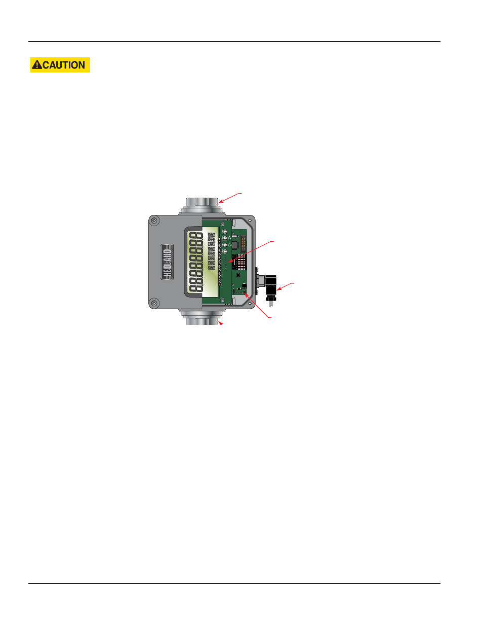
Outlet Port
Display Board
Transmitter
Connector
Sensor Board
Inlet Port
Figure 2: Terminology
MR Flow Transmitter
Page 8
November 2013