Installing the transmitter, Flow inlet port flow direction arrow, Figure 4: flow direction arrow – Badger Meter MR Transmitter User Manual
Page 10: Figure 5: installing the meter
Flo
w T
ran
sm
itt
er
35
00
PS
I/2
41
BA
RS
M
AX
OIL
Flow
Tra
nsm
itte
r
Model H600A
-000-MR
S.N.: 78500
Dat
e: 0412
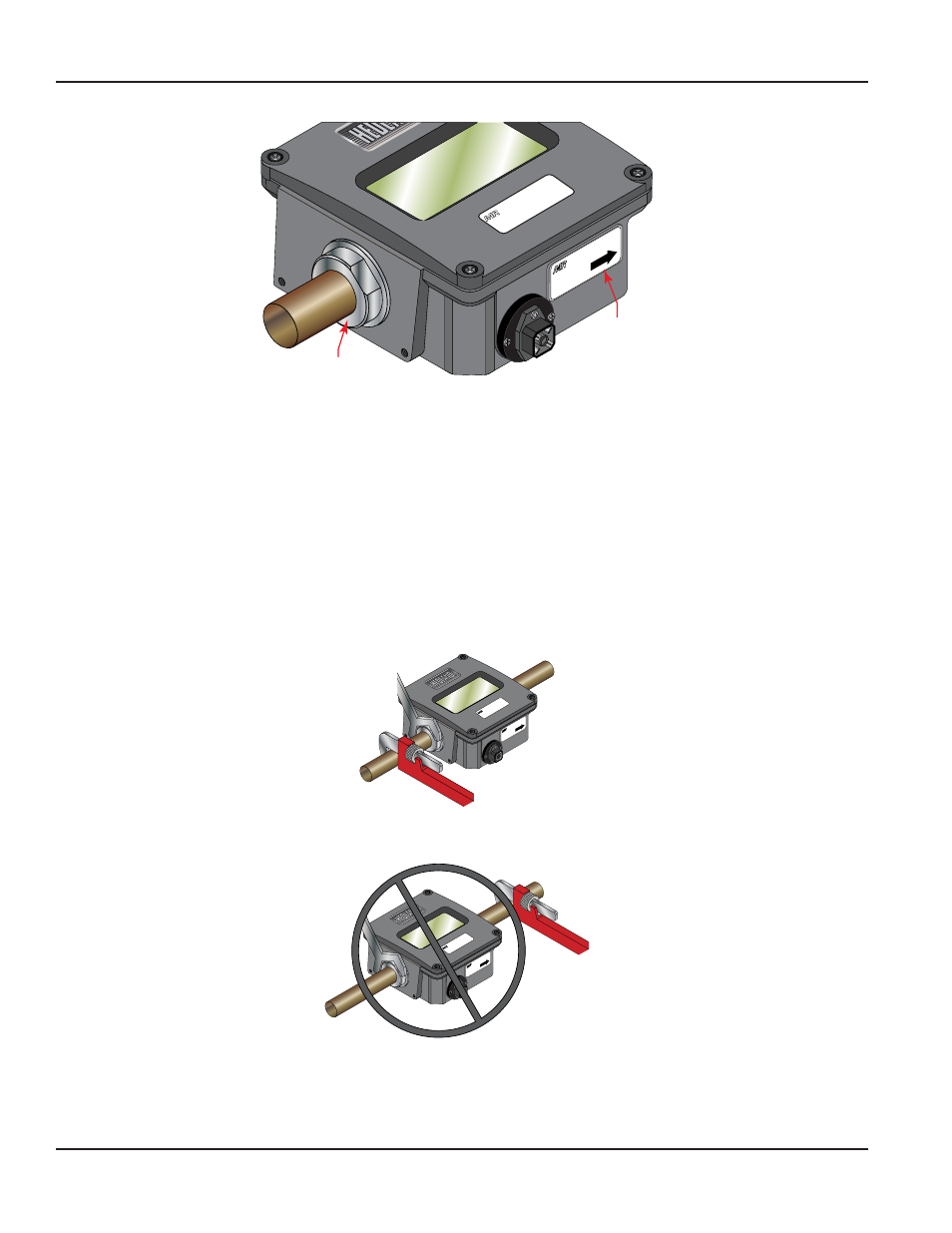
FLOW
Flow
Inlet Port
Flow
Direction
Arrow
Figure 4: Flow direction arrow
Installing the Transmitter
1 . Disconnect the electrical power from the target system before making or changing any transmitter connections .
2 . Use 0 .05 A fast-acting fuse if non-current limited power sources are used .
3 . Terminate cable shield connection at either DC ground or earth ground .
4 . Mount the transmitter so fluid is traveling in the direction of the flow arrow . See
5 . Install unit in desired location . Use wrench on transmitter flats to hold the unit in place during installation . DO NOT TURN
the transmitter using the wrench . See
.
6 . After installation, rotate the transmitter by hand to view the display . See
.
7 . Capture the zero flow position on the meter cone using the ZERO CAPTURE procedure .
Place wrench on transmitter flats on the same
side plumbing is being tightened
Never place wrench on transmitter flats
opposite plumbing being tightened
Flow
Tra
nsm
itte
r
Model H600A
-000-MR
S.N.: 78500
Dat
e: 0412
FLOW
Flo
w T
ran
sm
itt
er
35
00
PS
I/2
41
BA
RS
M
AX
OIL
Flow
Tra
nsm
itte
r
Model H600A
-000-MR
S.N.: 78500
Dat
e: 0412
FLOW
Flo
w T
ran
sm
itt
er
35
00
PS
I/2
41
BA
RS
M
AX
OIL
Figure 5: Installing the meter
MR Flow Transmitter
Page 10
November 2013