Badger Meter Flow-Alert Reed Switch User Manual
Page 13
Form #04-VAM-UM-00229 09/12
Page 13
gasket. To properly seat the
cover gasket, tighten cover
screws in a crisscross pattern
as shown in Figure 10 on page
10.
Reed Switch (Figure 14)
1. Disconnect the Hirschmann
connector and remove
connector from wires.
2. Remove screws securing cover
and remove cover.
3. Remove the two scale
mounting screws.
4. Remove the screws securing
the two mounting brackets
and remove the brackets.
5. Loosen the two slide bracket
screws.
6. Remove the switch mounting
screw and remove mounting
block/switch assembly from
slide bracket.
7. Remove the two mounting
screws securing switch to
mounting block and pointer.
Make note of switch position.
8. Install new switch to mounting
block and pointer using screws
removed in step 7.
9. Remove the strain relief.
10. Install mounting block/switch
assembly to slide bracket using
screw removed in step 6.
11. Tighten the slide bracket
screws.
12. Install strain relief.
13. Install mounting brackets to
scale using scale mounting
screws. Do not fully tighten
yet.
14. Secure mounting brackets
using screws removed in step
4.
15. Tighten screws installed in
step 10.
16. Solder Hirschmann connector
to new switch wires.
NotE: For ¼”, ½”, ¾” and 1” units, wire
should be cut to 5” length. For 1¼” and
1½” units, wire should be cut to 10”
length.
17. Install the front cover and
gasket. To properly seat the
cover gasket, tighten cover
screws in a crisscross pattern
as shown in Figure 10.
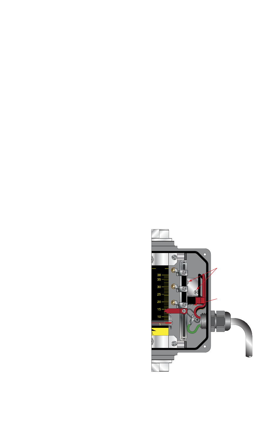
LPM
Mounting Bracket
Screws (Qty 2)
Snap Switch
Screws (Qty 2)
FIGURE 13 - MICRo SwItCH
REPlACEMENt