V. maintenance, Warning – Badger Meter Flow-Alert Reed Switch User Manual
Page 12
Page 12
Form #04-VAM-UM-00229 09/12
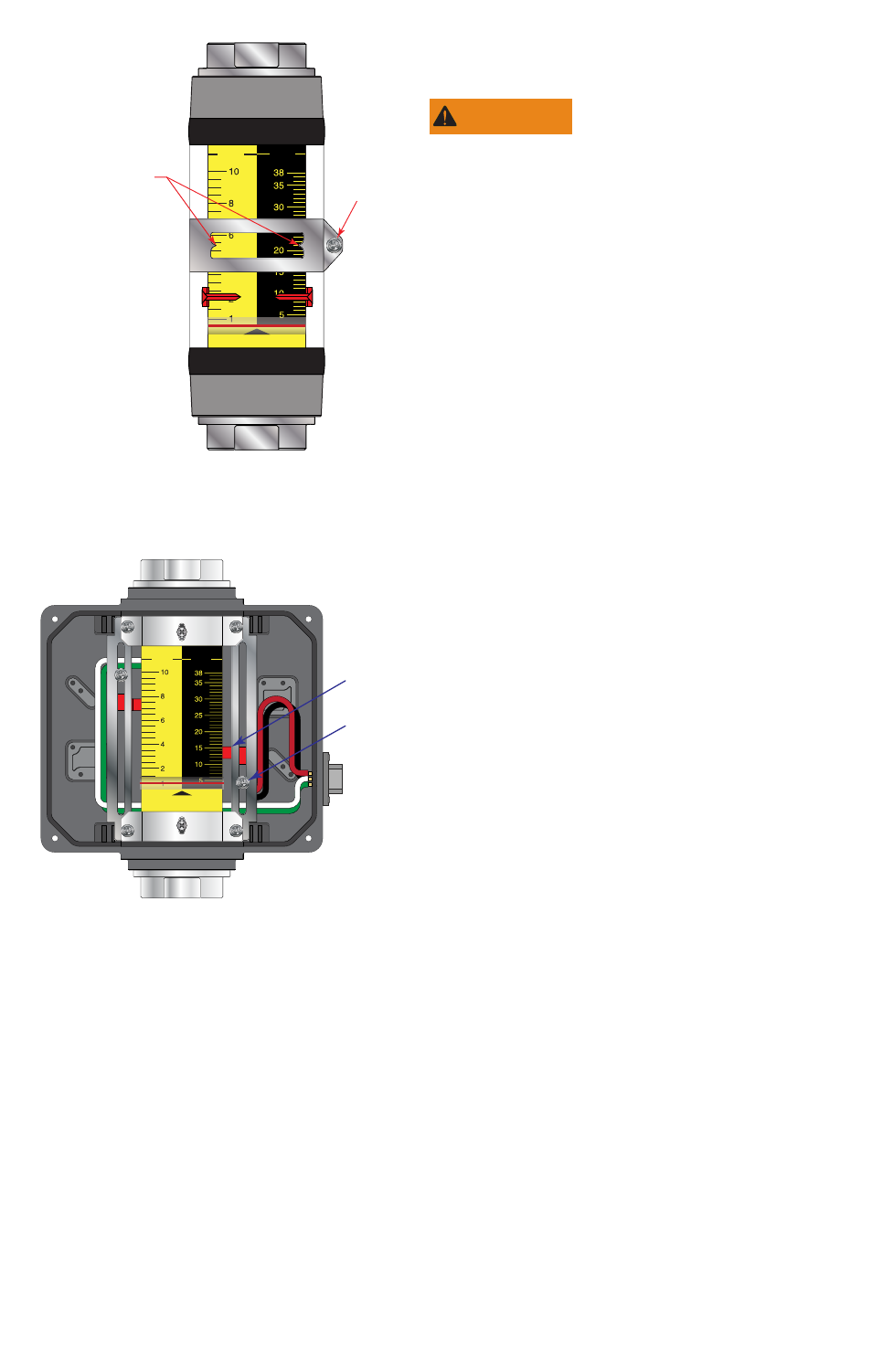
GPM
LPM
OIL
Screw
Arrow Pointers
on Switch Band
FIGURE 11 - REED SwItCH
ADJUStMENt - ¼” MoDElS
GPM
LPM
OIL
Arrow
Pointer
Screw
FIGURE 12 - REED SwItCH
ADJUStMENt FoR
¼” - 1½” MoDElS
(DUAl SwItCH SHowN)
V. MAINTENANCE
WARNING
Warning - Disconnect electri-
cal power before removing me-
ter cover. Failure to follow these
instructions could result in serious
personal injury or death and/or
damage to the equipment.
SWITCH REPLACEMENT
Micro Switch (Figure 13)
1. Disconnect cable connection
to the meter.
2. Remove screws securing cover
and remove cover.
3. Note the positions of the
colored wire connections on
the switch. Disconnect the
wires from the switch.
4. Remove the two mounting
bracket screws at the bottom
of the meter.
5. Remove mounting
bracket/switch assembly
from the meter. Remove the
two screws securing switch to
mounting bracket.
6. Install new switch to mounting
bracket using screws removed
in step 5.
7. Install wires to terminals on
switch as marked in step 3.
8. Install mounting bracket/
switch assembly to meter
using screws removed in step
4.
9. Install the front cover and