Badger Meter ORION AMR/AMI Hardware Solutions for Gas Utilities User Manual
Page 40
ORION® Fixed Network (SE) II Network Gateway Transceiver
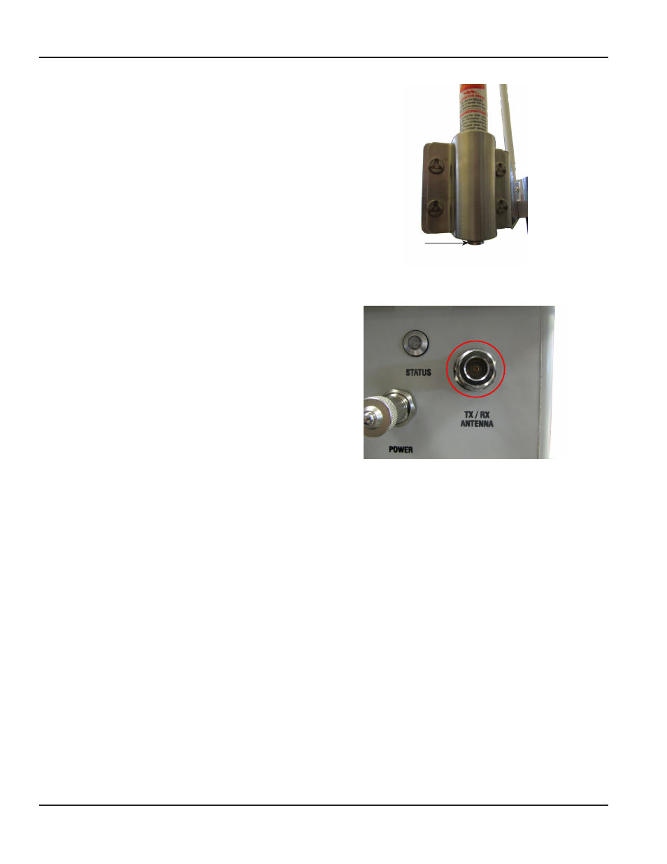
9 . Prepare each of the antenna cables and connectors
per manufacturer’s instructions and connect to
the Type N female connector at the bottom of
each antenna .
Tighten each Type N connector to
8…12 inch-pounds . To approximate this
measurement without a torque wrench, finger
tighten the Type N connector and then tighten an
additional 1/16 inch turn with pliers .
NOTE:
N
A lightning arrestor is recommended for all
remote antenna installations . See
for additional
information .
Figure 53: Type N female connector
10 . Collect the required VSWR readings after the
antennas are installed in their final locations .
Record the information on the form provided
by Badger Meter . See
11 . After the antenna tests are completed, connect the
TX/RX antenna to the Type N female connector on
the gateway enclosure (marked ”TX/RX Antenna’’) .
The antenna cable can be connected directly to the
enclosure . If needed, a 3-foot coaxial cable with
Type N straight standard male plugs, both ends,
(67628-001) can be used to transition from the
antenna connector to Type N female connector on
the enclosure .
Figure 54: TX/RX Antenna connector
12 . Loosen the four (4) captive screws on the gateway enclosure cover . Remove the cover, attach the internal backup
battery and reattach the cover . See
"Connect the Battery Backup" on page 9
if you need help .
13 . Wire the M12 connector according to the instructions provided (
"M12 Connector Assembly" on page 23)
and attach
the power cable to the gateway enclosure .
14 . Mount the backplate and the gateway enclosure using V-block mounting hardware or Band-IT banding kit as
"Using V-block Mounting Clamps" on page 14
for details .
Type N Female
Connector
Page 40
March 2014