Badger Meter ORION AMR/AMI Hardware Solutions for Gas Utilities User Manual
Page 24
ORION® Fixed Network (SE) II Network Gateway Transceiver
4 . Strip the ends of the six (6) colored wires to a length of 1/8 inch . Twist the conductors on each wire .
5 . Shorten the drain/bare wire (no insulation) to 11/16 inch .
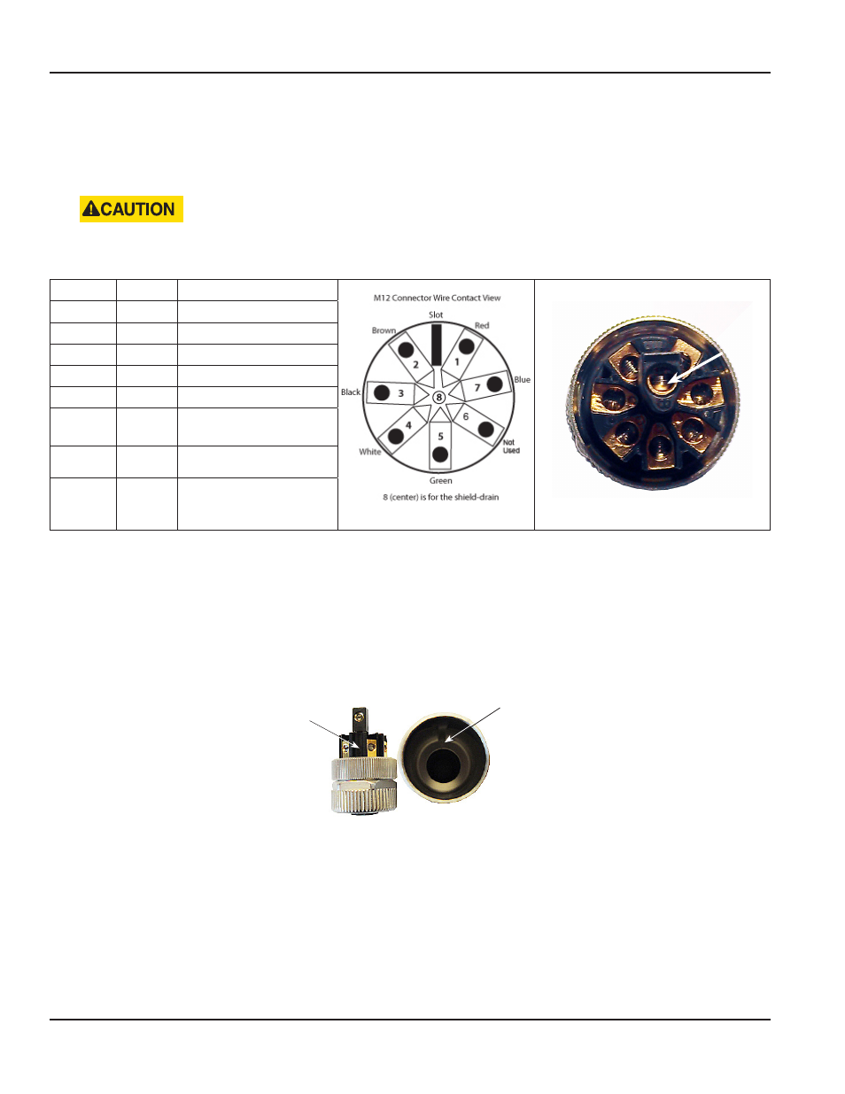
6 . Loosen each screw (about 2…3 turns) on the female insert and attach the wires to the female insert using the chart
below . Retighten each screw after the wire has been connected .
BE CAREFUL NOT TO BACK THE SCREWS OUT TOO FAR. THE SCREWS ARE SMALL AND CAN EASILY BE LOST IF THEY
ARE DROPPED.
Function
Wire
Female insert connector
Female Insert Diagram - Top View
Female Insert Photo - Top View
V DC+
Red
1
V DC–
Brown
2
V DC–
Black
3
RS232
White*
4
RS232
Green*
5
Not used
Not
used
6
V DC+
Blue
7
V DC–
Drain**
8 (Center)
* Used with the serial programming harness (66529-002)
** Used with shielded cable only
NOTE:
N
For additional information about DC power source, see
"Absolute Requirements" on page 20
7 . Assemble the female insert to the coupling sleeve by aligning the female insert tab slot with the notch in the
coupling sleeve .
Figure 24: Slot alignment
Female Insert
Tab Slot
Coupling Sleeve Insert
Notch
Slot
Brown
Red
Black
Blue
White
Not
Used
Green
Drain
Page 24
March 2014