Badger Meter ORION AMR/AMI Hardware Solutions for Gas Utilities User Manual
Page 25
Installation Manual
8 . Remove the cap from the M12 receptacle on the bottom of the gateway transceiver . The cap should be saved so it
can be replaced if the power cable is removed later .
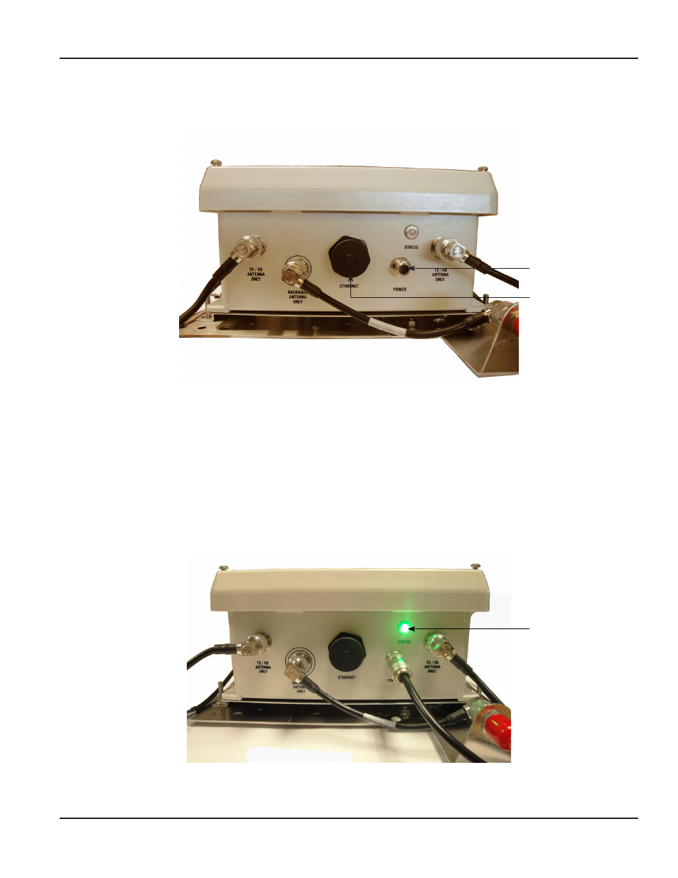
Figure 25: Bottom of gateway transceiver
9 . Connect the M12 plug connector assembly to the M12 receptacle and tighten the locking ring in a clockwise
direction until finger tight .
10 . Connect the 308 connector on the other end of the power cable to the 308 connector of the AC-to-DC power supply
and snap the anti-tamper collar over the connection .
11 . Connect the power cord to the power supply and then plug the three-prong male end of the power cord into a
120V AC power source . The LED indicator above the M12 connection turns on with a steady green light, indicating
the gateway power is on (Figure 26) .
NOTE:
N
A red blinking light indicates the gateway is being powered only by the internal backup battery .
No light indicates the gateway is not receiving power .
Figure 26: Powered gateway
The M12 connection is complete .
M12 Receptacle
with Cap Removed
RJ45 Receptacle
Steady green light
indicates gateway
power is on (not on
backup power)
Page 25
March 2014