Manual operation and override, Override, Automatic stroke adjustment – Warren Controls PICV Series User Manual
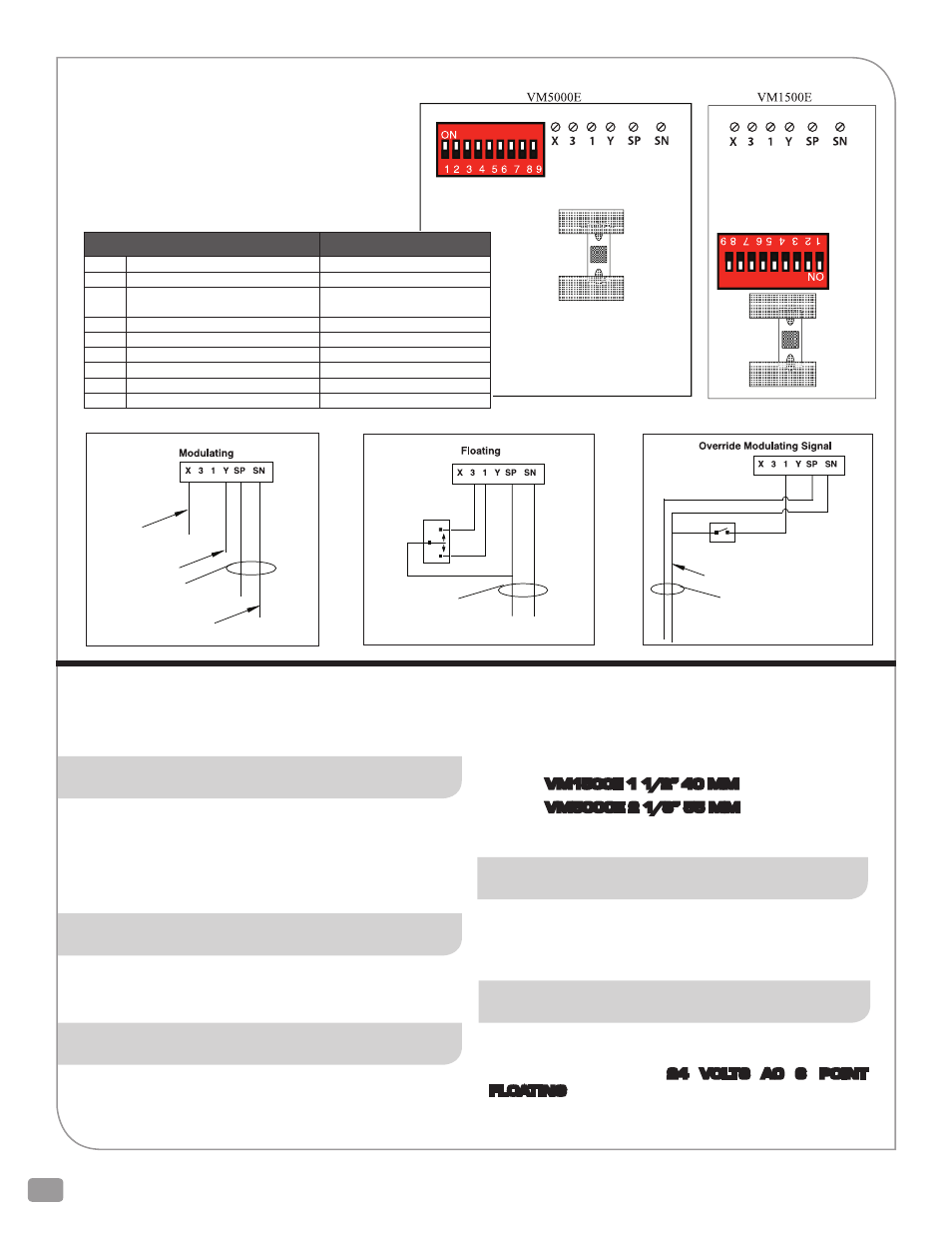
Page 16: Reset, Control signals, Set-up, Switch functions
16
2600 Emrick Blvd • Bethlehem, PA 18020 • USA • 800-922-0085 • www.warrencontrols.com
When the actuator settings are known, it is easier to make them
before the valve and actuator are installed in the system. When
power is first applied to the actuator, check to see that it moves
through its full range. If it does not, reset it by moving switch #9.
MANUAL OPERATION AND OVERRIDE
The actuator can be manually operated with a metric hex wrench. The
VM1500E uses a 4mm hex wrench. The VM5000E uses an 8mm hex
wrench. The socket is on top of the actuator. VM5000E actuators have
a clutch button that must be depressed while manually operating the
actuator. De-Energize the actuator before manual operation.
OVERRIDE
:
Connecting the neutral (terminal SN) to terminal 1 lowers the stem
and to terminal 3 raises the stem. This can be done by an external
switch or controller.
AUTOMATIC STROKE ADJUSTMENT
The stroke adjusts itself automatically. This happens the first time
power is applied or whenever the position of switch #9 is changed.
Adjustment takes several minutes during which the actuator will
move through its full stroke 2 or 3 times. The actuator remembers the
settings so a power failure does not cause the actuator to reset itself.
The automatic stroke adjustment does not work if the valve stroke
is greater than the limits of the actuator. The maximum strokes are:
VM1500E 1 1/2” 40 MM
VM5000E 2 1/8” 55 MM
Automatic stroke adjustment ensures that the signal range covers
the actual stroke of the valve.
RESET
Changing the position of switch #9 makes the actuator recalculate
the stroke. Do this if the actuator has been used on another valve,
tested without being on the valve, has been incorrectly mounted on
the valve, or has been taken off of the valve and reinstalled.
CONTROL SIGNALS
The actuator must be set for the control signal being used and
whether the signal is direct acting or reverse acting.
The acceptable signals are:
24 VOLTS AC 3
POINT
FLOATING
or any of the following proportional signals.
24 volts ac
Terminal 1 Stem down
Terminal 3 Stem up
Feedback Positive
0 - 10 or 2 - 10 Vdc
Control signal
Positive
24 volts ac
Common and control signal negative
If system is grounded, then ground SN
SET-UP
SP ........................ 24 volts AC power in
SN ....................... Common (Ground) and control signal negative
(See wiring diagrams)
Y .......................... Control signal in (Positive)
X .......................... Feedback signal out (Positive)
1 .......................... Override
3 .......................... Override
SWITCH FUNCTIONS
Switch OFF
ON
1
Voltage Control Signal
Milliamp Control Signal
2
2 - 10 Volts or 4 - 20 ma
0 - 10 volts or 0 - 20 ma
3
Direct Acting
Reverse Acting
(Extend on increasing signal)
(Retract on increasing signal)
4
Full Range
Split Range
5
Low Range Signal
High Range Signal
6
Proportional
3 Point Floating
7
Equal Percentage Valve (Default)
Linear Valve
8
(Default)
DO NOT USE
9
Reset
Reset
In the override position the Actuator is driven
to the end position. Connecting to terminal
1 drives the stem down. Connecting to
terminal 3 drives the stem up.
24 volts ac
Common and
control signal negative
Override