3 connecting peripherals – Thermo Fisher Scientific Alpha DO 500 User Manual
Page 11
Instruction Manual
Alpha DO 500
5
2.3 Connecting Peripherals
2.3.1 Connection
Terminals
Remove Back Cover:
Remove the screws from the four corners at the back of the DO Transmitter.
Remove the back cover. The connectors are exposed on the back PCBA as
shown in the Figure 1 below.
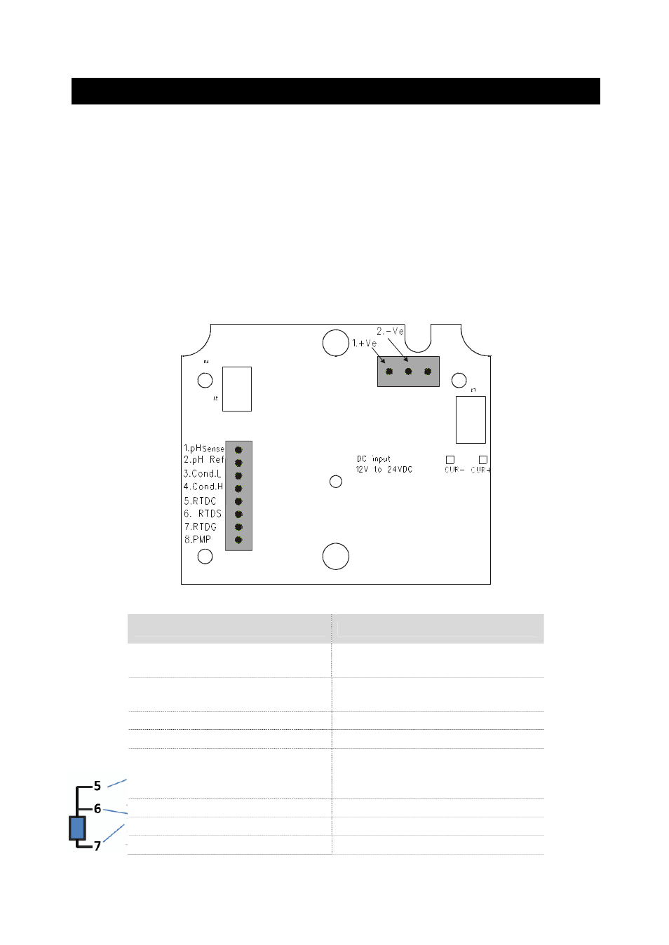
Connectors:
x SL2 – 12 to 24 V DC power
x SL1 – Dissolved Oxygen electrode & Temperature probe connections
(wiring has to be done in the detachable connector
SL1
SL2
Figure 1: Outer Side of Back PCBA
SL1 Connections
SL 2 Connections
1. DO Input, +ve terminal
1. DC Power Supply +ve
terminal
2. DO Input, -ve terminal
2. DC Power Supply –ve
terminal
3. No Connection
3. No Connection
4. No Connection
5. PT100 Compensate
(Short to pin 6 for 2-wire
RTD)
6. PT100 Sense
7. PT100 Ground
8. No Connection
- PCTestr 35 (2 pages)
- pHScan BNC (3 pages)
- pHScan 3/3+ (5 pages)
- pHTestr 1 (3 pages)
- pHTestr 10/20/30/10 BNC/Spear (2 pages)
- ORPTestr 10/10 BNC (2 pages)
- EC/TDS/SaltTestr 11 (4 pages)
- EC/TDS/SaltTestr (2 pages)
- ECScan High/Low & TDScan High/Low (9 pages)
- SaltTestr (2 pages)
- EcoTestr pH 2 (2 pages)
- EcoTestr pH 1 (2 pages)
- EcoTestr EC High (2 pages)
- EcoTestr EC Low (2 pages)
- EcoTestr TDS High (2 pages)
- EcoTestr TDS Low (2 pages)
- EcoTestr Salt (2 pages)
- Eutech pH 5/6 Plus & Ion 6 Plus (New version R1.1, SN >797406) (23 pages)
- Eutech pH 5/6 Plus & Ion 6 Plus (Old version EP6, SN <797406, discontinued) (23 pages)
- Eutech COND/TDS/Salt 6 Plus (40 pages)
- Eutech DO 6 Plus (48 pages)
- EcoScan pH/Ion 5 & 6 (27 pages)
- EcoScan CON 6 & TDS 6 (56 pages)
- EcoScan CON 5 & TDS 5 (18 pages)
- EcoScan Salt 6 (40 pages)
- EcoScan DO 6 (80 pages)
- CyberScan pH 10/pH 100 (67 pages)
- CyberScan pH 11/pH 110 (76 pages)
- CyberScan CON 10/CON 100/CON 200 (62 pages)
- CyberScan CON 11/CON 110 (80 pages)
- CyberScan DO 110 (60 pages)
- CyberScan PCD 650 (127 pages)
- CyberScan CON 400/410 (For units manufactured before March 2010, discontinued) (60 pages)
- CyberScan CON 400 (For units manufactured from March 2010 onwards) (60 pages)
- CyberScan pH 300/310 (52 pages)
- CyberScan DO 300 (60 pages)
- CyberScan PC 300 (72 pages)
- CyberScan PD 300 (76 pages)
- CyberScan PC 10 (31 pages)
- C401 Colorimeter (64 pages)
- TN100 Turbidimeter (31 pages)
- RS232C Interface Adapter (9 pages)
- Thermo Scientific Temp 360 (44 pages)
- Thermo Scientific Temp 340 (40 pages)
- Thermo Scientific Temp 300 (32 pages)