Attaching gauges, Rs232c output format – SHIMPO FGS-250PV User Manual
Page 9
9
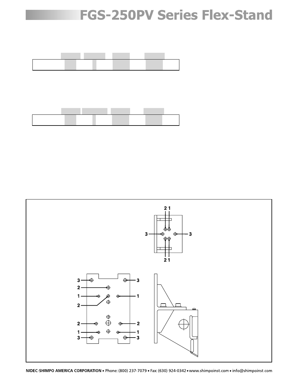
Attaching Gauges
Attaching a Force Gauge to the Force Gauge Plate
This plate should be attached to the test stand using M6 threaded screws. Hole position is selected according to
force gauge model used. See the plate illustration below for attachment details.
1. FGV/E series
2. DFS series
3. FGV-H/FGE-H
RS232C Output Format
SING/CONT Mode
Counter Direction
Force
Distance
ZZ{Space}0003{Space}A{Space}-0021.5{Space}+032.8{Cr}
NOTE: Direction B: PUSH, A: PULL
Data will be sent when stand reaches a manual limit switch or a programmed force limit.
PROG Mode
Counter Program #
Force
Distance
ZZ{Space}0003{Space}1{Space}-0021.5{Space}+032.8{Cr}
Data will be sent when the test stand force gauge/load cell platform reaches every set position or if a load exceeds
the force limit.
NOTE: If the auto zero function is selected, data will be output at the first zero position, when the test stand force
gauge/load cell platform reaches every set position (except the set point zero position), or if the force gauge exceeds
a force limit.