SHIMPO FGS-100-PXL User Manual
Page 3
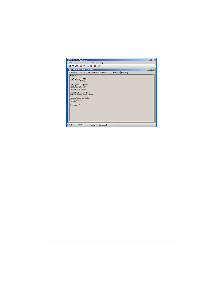
Configuration Parameters
Figure 2. Gray Configuration window
The Gray Configuration window (Fig 2) displays parameters from a configuration that is NOT currently
uploaded to the Platform but has been opened by the PC Program. This window displays parameters that
determine test measurement start and return events. This section describes these parameters and
how they are used. Reference the "Edit Test Configuration" section for changing these values.
Data Version - a system parameter, cannot be defined by the user.
Max Test Force - this value determines when the "return" event occurs. The return event terminates the
inward direction and reverses the motor to the outward direction. The max limit for this parameter is
defined by the transducer that is currently mounted on the Platform.
Touch Force - this value determines when the "start" event occurs, which triggers the system to begin
logging measurements. The start event is when the system recognizes the UUT has been contacted
by the transducer. The min limit for this parameter is defined by the transducer that is currently
mounted on the Platform.
Test Speed - a calculated parameter, cannot be directly set by the user. Other settings affect this value.
Step Delay Time - this value adds additional time to the internal fixed delay time the platform waits
between motor steps.
Step/Data Sample - this value determines how often the system takes a measurement. The range for
this parameter is 1 (default) to 10, signifying the system can take a measurement every motor step up to
one measurement every 10 motor steps. This value affects overall system displacement resolution.
and may need adjustment based on test requirements. The system can log and store a maximum of
5000 entries. With the standard lead screw and default settings total displacment is 6.35mm (0.250 inch).
Changing this value to 10 will increase the total displacement to 63.5mm (2.50 inch).
Step Size - a calculated parameter, cannot be directly set by the user. Other settings affect this value.
Stop @ Displacement - setting this value to "True" enables the platform to limit displacement at the
Max Displacement setting. The default value is "False".
Max Displacement - if the Stop @ Displacement value is true this value sets the displacement limit.
If the Max Displacement is reached before the Max Test Force then this value becomes the return
event trigger.
Microstepping - this value affects the displacement distance (Step Size) of the lead screw for each
motor step. There are 3 values available; 2 (default), 4 and 8. With the standard lead screw and a
microstep value of 2 the displacement distance is 0.0025mm (0.0001 inch) for each motor step.
Measure Resistance - this option currently is not available for the Model 925, therefore this value is
always false and the Channels value is always 1.
Comments - a user text field. Text entered here will be attached to the measurement data.
3