SHIMPO FG-7000-Series User Manual
Page 6
3. CHARGING
The FG-7000 Series Digital Force Gauge is supplied with a set of 3
Nickel Metal Hydride AAA rechargeable batteries, which are sup-
plied fully charged to allow immediate use. Users need to recharge
batteries when a low battery icon flashes. Users should connect
the gauge and the charger using the USB cable. Then connect
the charger to an AC socket to start charging. Laptops and other
USB devices can also charge the gauge. A fully charged battery
pack will provide approximately 16 hours of constant use.
Rechargeable battery pack:
- Type: Ni-MH 3.6VDC 800mAH rechargeable batteries
-Charging time: approx. 3~4 hours
-Battery life: approx. charge and discharge 500 times
4. COMMUNICATIONS
4.1 USB
The FG-7000 Series Digital Force Gauge is designed in accor-
dance with USB2.0 standard protocol. (Figure 4.1) The USB Port
can be connected to a charger with the USB cable for charging
the internal Ni-MH battery and can be connected to a computer
for uploading the measured values. Connect the gauge and the
computer with the USB cable, then open the computer software.
Upload the values. Please refer to the software manual for addi-
tional information.
4.2 Port Pin Assignments
Table 4-1
Figure 4-1
4.2.1 RS232
The RS232 serial port is used to connect a printer to print the
memory data.
RS-232 specifications are as follows:
-Data transmission: serial interface
-Synchronization: asynchronous
-Signal Level: RS-232 level, logic 1:-5v, logic 0: +5v
-Hardware Flow Control: None
-Data word length: 8 bits
-Stop bit: 1bit
-Parity: None
-Baud rate: 38400
4.2.2 Comparison Output
Comparison Output internal circuit shown as Figure 4-3.
Figure 4-3
When the measured value is less than the lower limit tolerance
value, the “pc2” operates, 7pin and 6pin line conduction. When
the measured value is more than the upper limit tolerance value
or 110% of the rated capacity, the “pc1” operates, 4pin and 6pin
line conduction. Maximum permissible voltage: 7pin to 6pin, 4pin
to 6pin 35V; 6pin to 7pin, 6pin to 4pin 6V.
PIN#
Definition
1
RS232-Transmit
2
RS232-Receive
3
RS232-Ground
4
Comparison Output B
5
Reserved
6
Comparison Output C
7
Comparison Output A
8
Reserved
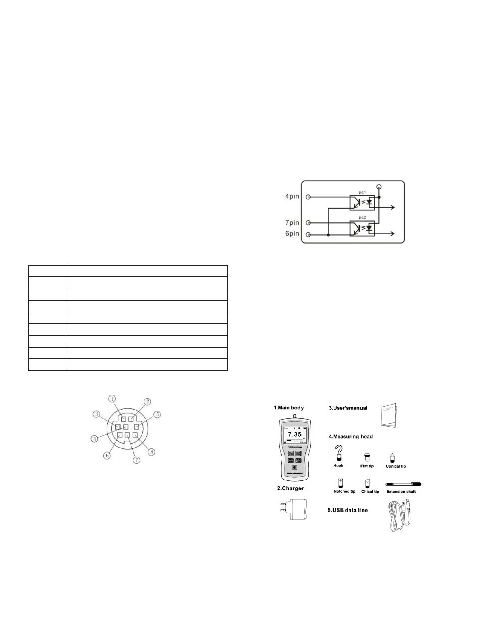
5. MISC.
5.1 Accessories
6