KROHNE BM 100A Handbook User Manual
Page 19
Handbook BM 100 A
19
2.2.2 Wiring
connections
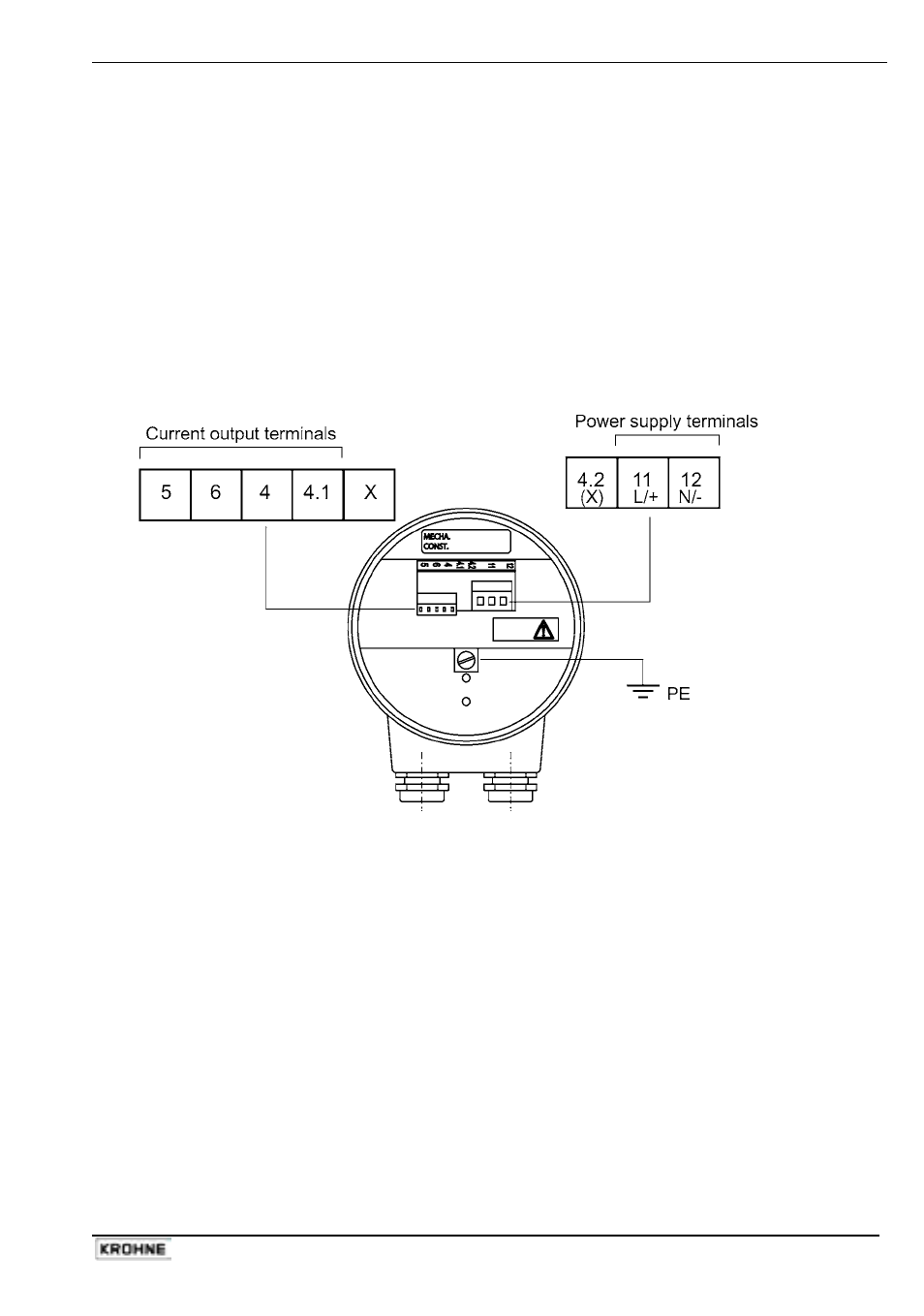
Open the signal converter housing rear cover, using the plastic wrench supplied. The terminal
connections are labelled. The standard connections are shown below.
Before starting to wire:
• check that the power supply corresponds to the power board installed.
• check which output option you have selected: this will be indicated on the underside of the rear
housing cover and on the gauge nameplate.
Terminal layout : non – Ex version
X = Terminal not used (X) = Terminal not used except for RS485 outputs
Ensuring a good contact and protection of wire strands
Local regulations concerning electrical wiring must be followed and obeyed. If no details are
given, we recommend :
• crimped metal sheaths over the wire strands
• power supply cables should be rated for at least 500 V, with a cable diameter of 0.5 to 1.5
mm / 0.02” to 0.06” (non-Ex applications only).
• the output current cable diameter should be from 0.5 to 0.75 mm / 0.02” to 0.03”
PE Ground Terminal notes
The internal earth connection shall be used according local applicable installation standards, in
Europe the Low voltage Standard prescribes the connection of the yellow/green cable in case of
230VAC.