Table 3. remote voltage (rv) adjustment range, Figure 5. connections for remote voltage control, 3 remote turn on-turn off – KEPCO RKE 1500W Series Operator Manual User Manual
Page 9: Connections for remote voltage control, Remote voltage (rv) adjustment range, 5 (a), Re 5 (b), R. 4.3) and ref
RKE 1500W 021913
7
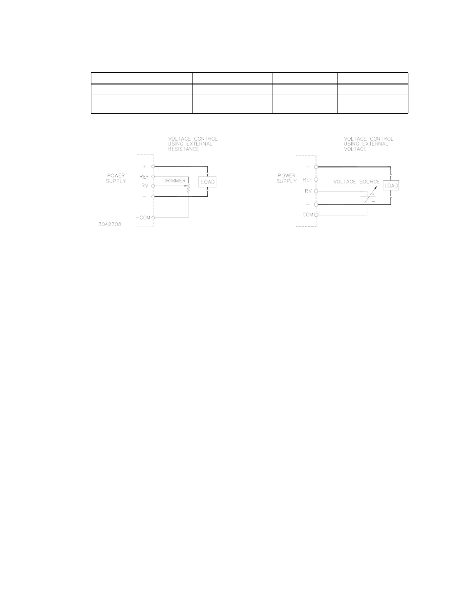
FIGURE 5. CONNECTIONS FOR REMOTE VOLTAGE CONTROL
4.3
REMOTE TURN ON-TURN OFF
When power is ON at the source, the output may be turned ON or OFF with the remote control feature
using the ±RC terminals (see Figure 4). These terminals accept a logic level (2.4V to 24V “high” and
0.0 to 0.4V “low”), or a contact closure. When the ±RC terminals are open, using either a mechanical
switch or a high level logic signal, the RKE 1500W output is cut OFF. When the RC terminals are
shorted, the output returns to within specifications. At low level logic, the maximum source current is
1.6mA and at high level the sink current is 1.0mA. The RC terminals must remain shorted if remote ON-
OFF is not used. The RC terminals are isolated from both the AC input and DC output terminals.
5.
ALARM FUNCTIONS
5.1
POWER FAIL SIGNAL (OPTICAL COUPLER OUTPUT ALARM CIRCUIT)
The default state of the alarm is logic low: the optocoupler conducts and the green front panel LED is
ON (see Figures 6 and 7). The sink current for the optocoupler is 50mA maximum, the maximum col-
lector to emitter saturation voltage is 0.40 Volts, and the collector to emitter voltage is 40 volts maxi-
mum. When output voltage drops to less than 80% of programmed voltage (5V or less for 36V model),
PF circuit output goes HIGH (optocoupler output transistor in open state), and the front panel LED goes
OFF. The PF terminals are isolated from the AC and DC output input terminals. Insulation resistance
between the PF terminals and the AC input terminals is the same as the insulation resistance between
the input and output. Insulation resistance between the PF terminals and the output terminals is the
same as the insulation resistance between the output and ground.
TABLE 3. REMOTE VOLTAGE (RV) ADJUSTMENT RANGE
RKE 24-50K
RKE 36-42K
RKE 48-32K
Remote Voltage RV (Volts)
3.5 - 6.5
0 - 5.75
3.5 - 7.5
Output Voltage, % of Vo (nomi-
nal)
70 - 130
17 - 153
70 - 115
A
B