1 scope of manual, 2 description, Mounting positions for the rke 1500w power supply – KEPCO RKE 1500W Series Operator Manual User Manual
Page 3
RKE 1500W 021913
1
1.
INTRODUCTION
1.1
SCOPE OF MANUAL
This Operator's Manual covers the installation and operation of the Kepco RKE 1500W Series of PFC
(Power Factor Corrected), RoHS (Reduction of Hazardous Substances) compliant, switching power
supplies. For service information, write directly to: Kepco Inc., 131-38 Sanford Avenue, Flushing, New
York, 11355, U.S.A. Please state Model Designation and Serial Number of your RKE Power Supply.
This information can be found on the nameplate of the unit.
1.2
DESCRIPTION
The Kepco RKE 1500W Series consists of three models of switching power supplies, each with a single
output as shown in Table 1. Units include PFC (power factor correction) at the input and may be oper-
ated with a nominal 100V a-c to 240V a-c (input voltage range 85 to 265 Va-c), 50-60 Hz (input fre-
quency range 47-66Hz). The RKE 1500W Series employs a light weight ferrite core with 135 KHz
switching frequency. Regulation is provided by pulse width modulation. A power stage with two MOS-
FETS on each side of the primary winding, operating in the forward mode, provides a smooth isolated
d-c output. A thyristor circuit prevents excessive turn-on current surge. Overvoltage protection and an
isolated remote TTL ON-OFF control are provided. An LED “output voltage ON” light and an output
voltage adjust trimmer are visible below the control terminals (left side of the case). Units are manufac-
tured on a steel frame with a steel cover.
2.
SPECIFICATIONS
Table 1 contains specifications and operating limits of individual RKE 1500W Series models. Table 2
contains specifications and operating limits common to all RKE 1500W Series Models. These specifi-
cations are at nominal input voltages at 25°C unless otherwise specified.
3.
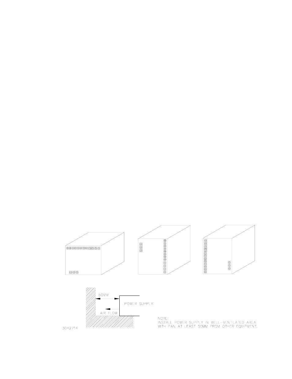
INSTALLATION
See Figure 1 for allowable mounting positions and orientation. See Figure 2 for mechanical outline
dimensions.
FIGURE 1. MOUNTING POSITIONS FOR THE RKE 1500W POWER SUPPLY