1 voltage adjustment, 2 remote voltage control, 1 voltage adjustment 4.2 remote voltage control – KEPCO RKE 1500W Series Operator Manual User Manual
Page 8
6
RKE 1500W 021913
NOTE:
If remote ON/OFF is not being used, ±RC terminals must be connected (use shorting link
supplied) for unit to operate.
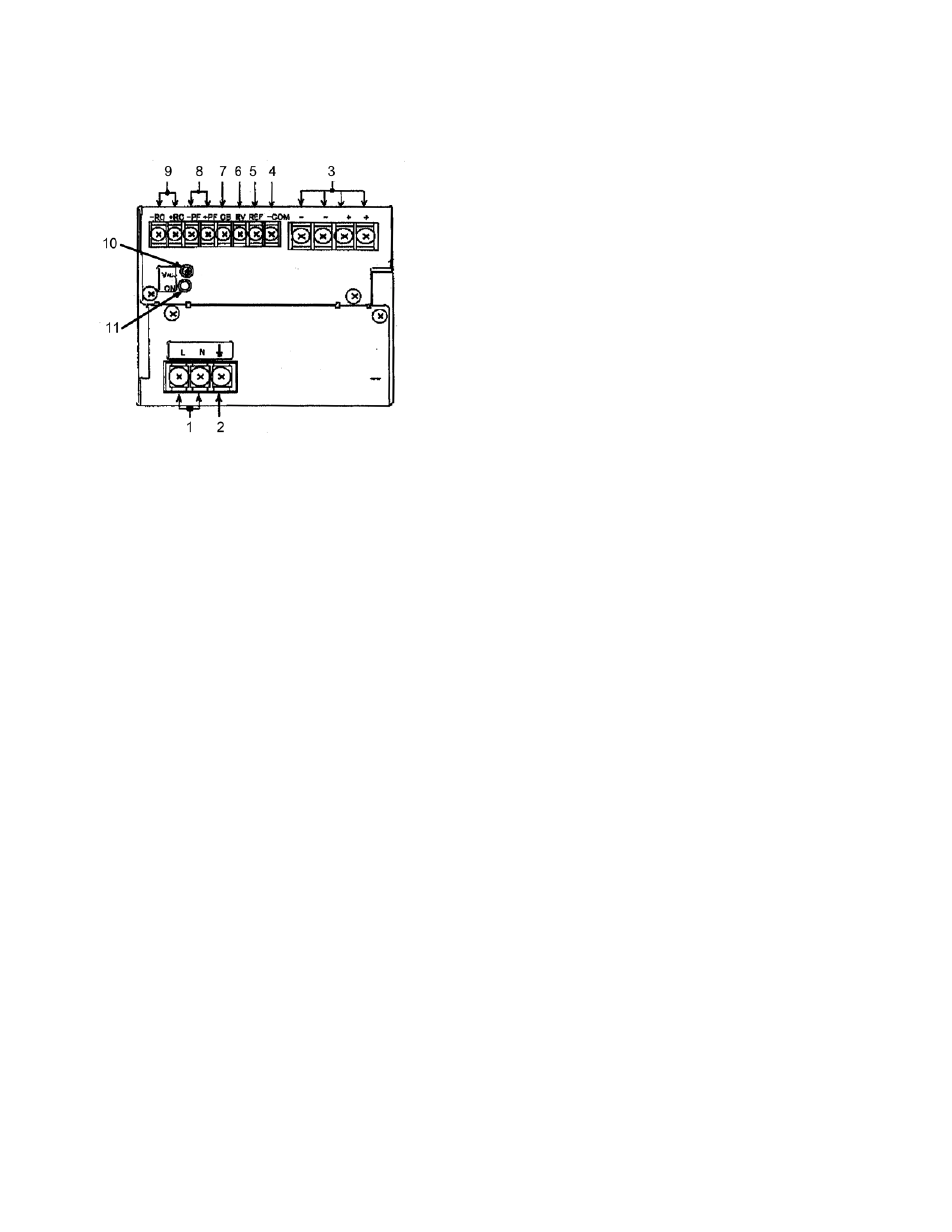
FIGURE 4. LOCATIONS OF OPERATING CONTROLS, INDICATORS AND TERMINALS
4.1
VOLTAGE ADJUSTMENT
Output voltage can be manually adjusted with the voltage adjustment control, Vadj (see Figure 4). To
adjust voltage, first place the unit under an operating load, then monitor the (+) and (–) output terminals
with a precision voltmeter and turn the voltage control to the desired operating value. Refer to Table 1
for the recommended Adjustment Range of all the RKE 1500W Models
4.2
REMOTE VOLTAGE CONTROL
The unit is shipped with a shorting link in place between RV and REF terminals Removal of this link
allows the output voltage to be adjusted by either a trimmer pot (resistance) or by an external variable
voltage source across the RV terminal and COM terminal.
NOTE:
Specifications are met when voltage is within adjustment range in Table 1. If remote voltage
control is not implemented, the shorting link between RV and REF must be in place
RESISTANCE: Use a shielded wire 6.6 feet (2M) maximum in length, for connection (of REF, RV, and
–COM terminals) to the trimmer control. Connect the external trimmer as shown in Figure 5 (A). Sug-
gested value for the trimmer control is 5K ohms. With the external trimmer control at its maximum
clockwise position, set the output voltage to the desired maximum value by adjusting Vadj clockwise.
The output voltage adjustment range is from 70 to 130% for the 24V model, 17 to 153% for the 36V
model, and from 70 to 115% for the 48V model.
VOLTAGE. By adjusting an external 3.5 to 6.5V voltage source the 24V model can be adjusted from 70
to 130% of the nominal output. By adjusting an external 0 to 5.75 voltage source the 36V model can be
adjusted from 17% to 153% of the nominal output. By adjusting an external 3.5 to 5.75V voltage source
the 48V model can be adjusted from 70 to 115% of the nominal output. Remove the shorting link between
the REF and RV terminal. Connect the voltage source across the RV and –COM terminals as shown in
Figure 5 (B).
LEGEND:
1. AC input terminals (L, N): Connect to AC, 100 to 240V,
input line.
2. Frame Ground (earth) terminal: Connect to earth ground.
This terminal is connected to the case.
3. DC output terminals (+, -): Connect to load (see Figure 8).
4. Signal Common (-COM): Provides return for REF and RV
signals
5. Reference Voltage (REF): Using the REF terminal
(together with the RV terminal), all the output voltages of
slave power supplies can be controlled by one voltage
adjustment of a master power supply (normally it is shorted
with a metal shorting link to the RV terminal).
6. Output Voltage Adjust (RV): This terminal (together with
the REF terminal) is used for remotely controlling output
voltage (see PAR. 4.2).
7. Current Balance (CB): This terminal is used when several
power supplies are connected in parallel (see PAR. 6.2).
8. Power failure (+PF, -PF): These terminals output an open
logic signal if output voltage drops to 80% or lower of a set
voltage (5V or lower for 36V model), or if output voltage is
shut down due to overvoltage or current limit protection, fan
speed failure, or overheating. (see Figure 7).
9. Remote ON-OFF (+RC, -RC): Output is turned ON-OFF by opening-shorting the RC terminals (output OFF when
open). RC terminals are isolated from input and output terminals. Normally, ±RC terminals are shorted with a metal
shorting link (see PAR. 4.3).
10. Output voltage adjustment trimmer (V.ADJ): Adjusts output voltage.
11. Output ON indicator: This green LED lights when output voltage is more than 80% of the programmed voltage.
NOTE Unit is shipped with shorting links (not shown)
connecting +RC to –RC (see PAR. 4.3) and REF to
RV (see PAR. 4.2)