Figure 6. output alarm circuit optically isolated, Figure 7. rke 1500w power failure timing diagram, 2 overvoltage and overtemperature protection – KEPCO RKE 1500W Series Operator Manual User Manual
Page 10: 3 current limit/overcurrent protection, Output alarm circuit optically isolated, Rke 1500w power failure timing diagram
8
RKE 1500W 021913
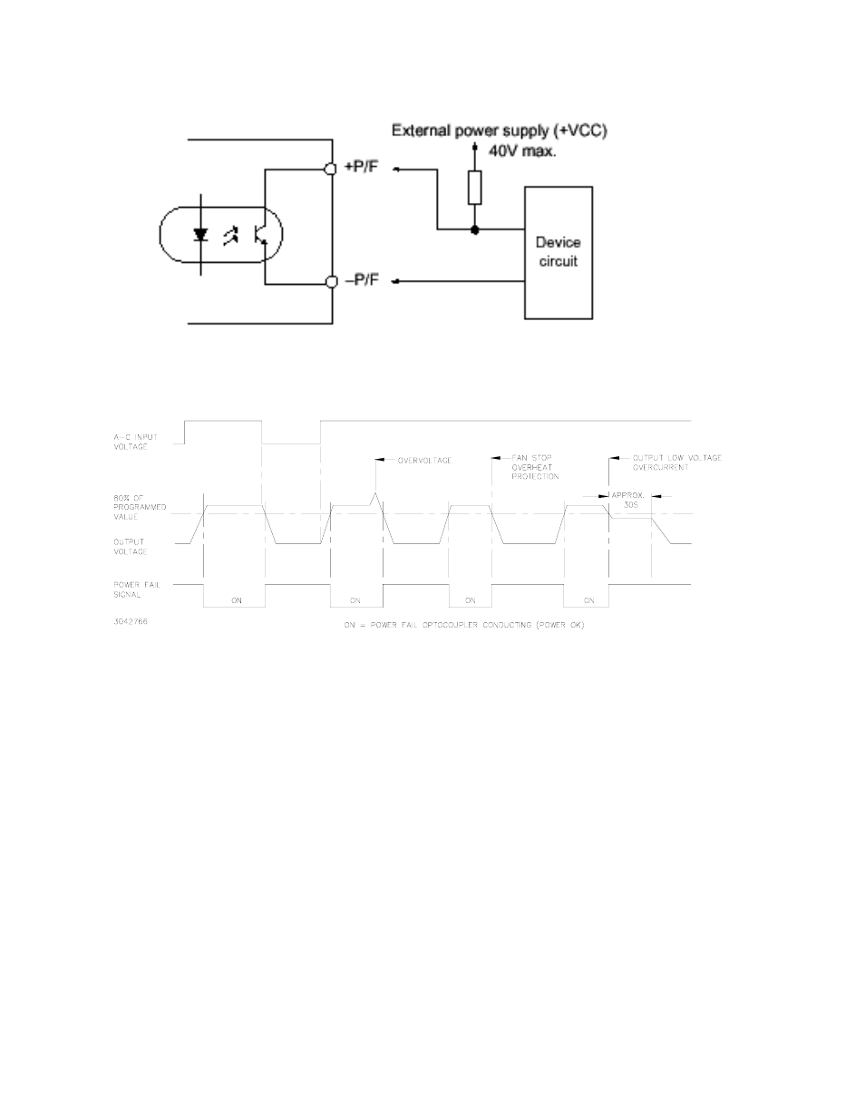
FIGURE 6. OUTPUT ALARM CIRCUIT OPTICALLY ISOLATED
FIGURE 7. RKE 1500W POWER FAILURE TIMING DIAGRAM
5.2
OVERVOLTAGE AND OVERTEMPERATURE PROTECTION
When the output voltage of the RKE 1500W Power Supply increases beyond the specified values (see
Table 1), the output is cut OFF and the fan turns OFF. To restart (reset) the unit, remove AC input
power, wait approximately 30 seconds, then reconnect AC input power; or open the RC terminals and
then reclose the terminals.
When the internal temperature of the RKE 1500W Power Supply increases beyond the specified values
(see Table 1), the output is cut OFF and the fans turn OFF. The restart cycle (Power ON) should not
begin until the temperature returns to within specifications. To restart (reset) the unit, remove AC input
power, wait 40 seconds, then reconnect AC input power. The power supply cannot be reset using the
remote ON-OFF feature unless the power supply is first shut down for 30 seconds and then turned on
again.
The alarm circuit is a diode transistor optical coupler. The transistor is normally conducting. When the
alarm is activated, the transistor cuts off and the collector emitter circuit is open (see Figure 6)
5.3
CURRENT LIMIT/OVERCURRENT PROTECTION
From 170 to 265V a-c input, the output characteristic of the power supply is a square type, and the unit is
set to shut down if output current exceeds specifications (see Table 1) for more than 30 seconds and
undervoltage detection is present (see PAR. 5.5). From 85 to 170V a-c input, operation (including alarm
signals) is intermittent when current limit condition occurs. To restart (reset) the unit, remove AC input