4 fan failure, 5 undervoltage, 1 connecting the load – KEPCO RKE 1500W Series Operator Manual User Manual
Page 11: 2 parallel connection, Correct and incorrect methods of load connection, Re 8, R. 5.5). from
RKE 1500W 021913
9
power, wait 30 seconds, then reconnect AC input power. or open the RC terminals and then reclose the
terminals. (see PAR. 4.3).
5.4
FAN FAILURE
A cutoff of the fan supply voltage causes the output to shut down and the fans to turn OFF. Fan failure
and all the other protection circuit operations are indicated by an open circuit across the (±) PF termi-
nals. To restart (reset) the unit remove the AC input power, wait 40 seconds, then reconnect AC input
power; or open the ±RC terminals and then reclose the terminals. If fan rotation is out of specification
the power supply will not recover.
5.5
UNDERVOLTAGE
If the output voltage of the power supply falls below 60 percent of the rated voltage for 30 seconds (5V
for the 36V model) while overcurrent is detected (see PAR. 5.3), the power supply shuts down and the
power failure alarm (see PAR. 5.1) will go to the high logic state. To restart (reset) the unit remove the
AC input power, wait 40 seconds, then reconnect AC input power; or open the ±RC terminals and then
reclose the terminals.
6.
LOAD CONNECTION
6.1
CONNECTING THE LOAD
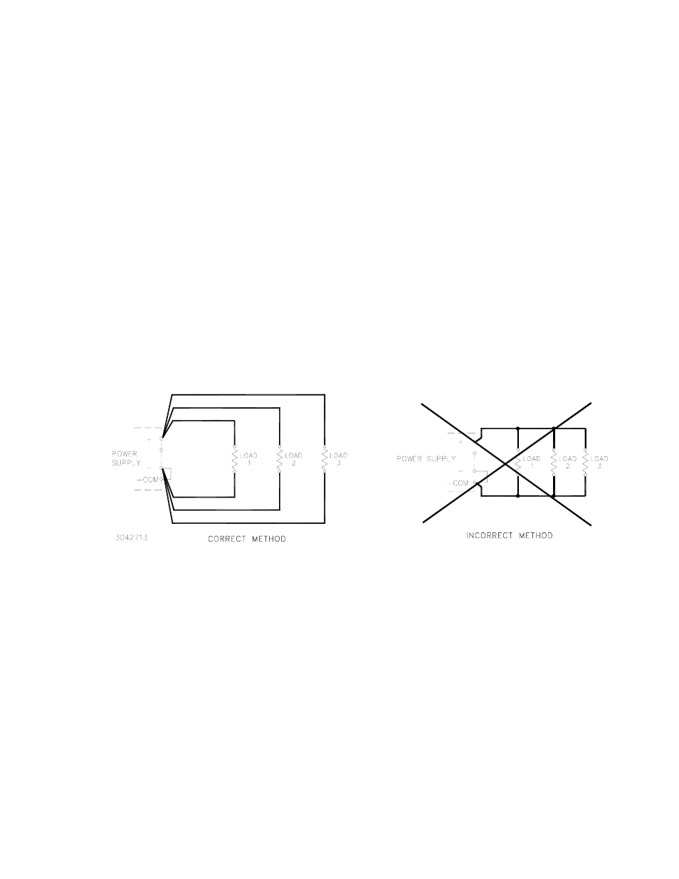
The load is connected across DC output (+) and (–) terminals (see Figure 8).
FIGURE 8. CORRECT AND INCORRECT METHODS OF LOAD CONNECTION
6.2
PARALLEL CONNECTION
RKE 1500W Power Supplies can be connected in parallel (with or without N+1 redundancy). The
impedance of the load wires between each power supply and load should be the same.
Figure 9 illustrates connection of up to four (maximum) power supplies in parallel. Output current for a
parallel connection operating into a single load is equalized by connecting the CB terminals as shown.
For a single remote ON-OFF signal to turn off all parallel-connected units, connect together all +RC ter-
minals and connect together all –RC terminals (see PAR. 4.3).
The current equalization with up to four RKE 1500W units in parallel should be within 20 to 90% of the
total output current rating. The output voltage of any Power Supply individually must be within 2% max-
imum of the other power supply output voltage setting. The expected current sharing is such that the
output current variation for each power supply is less than or equal to 10% of each power supply rated
output current.
N+1 Redundancy. An N+1 system requires one additional power supply than necessary to supply the
load. If one of the parallel-connected units fail, the others will continue to provide power to the load
without down time. For redundancy, add isolation diodes as shown in Figure 9.