3 series connection, Figure 12. series connection, 4 preliminary electrical check – KEPCO RKE 1500W Series Operator Manual User Manual
Page 13: Parallel connection, master-slave, single load, Series connection
RKE 1500W 021913
11
the load current (see PAR. 6.2.1). NOTE: Use shielded wire for connections to RV terminals. Match
impedance of load wires between each power supply and load by using the same wire lengths and wire
sizes.
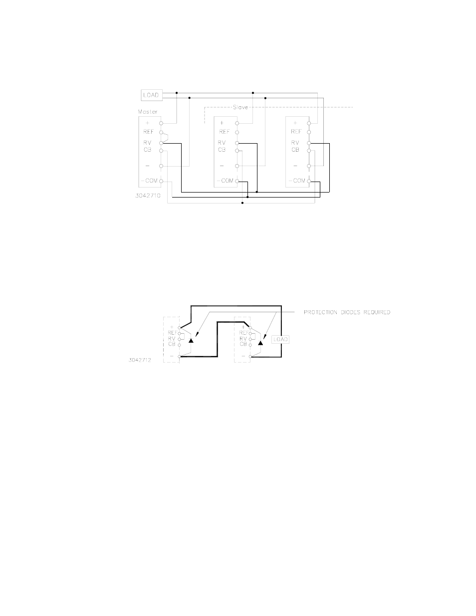
FIGURE 11. PARALLEL CONNECTION, MASTER-SLAVE, SINGLE LOAD
6.3
SERIES CONNECTION
Units may be connected in series to obtain higher voltages. When a number of power supplies are
operating in series, the current rating is to be limited to the rating of the power supply with the lowest
rating. Each Power Supply in series should be protected by a diode connected in parallel with the out-
put as shown in Figure 12. The diode protects against reverse voltages. It should be rated for typically,
V
REVERSE
>/= 2 x
Σ
V
OUT
of the series connection, I
FORWARD
>/= 2 xI
OUT
of the series connection).
FIGURE 12. SERIES CONNECTION
6.4
PRELIMINARY ELECTRICAL CHECK
Connect an adjustable load across the power supply DC output terminals, on the right side of the front
panel (see Figure 4). The load must have a dissipation rating of at least 3000 Watts. Connect a voltme-
ter and an oscilloscope across the power supply DC output (+) and (–) terminals. The oscilloscope
must be isolated from the source and grounded at the load. Use an isolation transformer between the
test equipment and the AC input power (see Figure 13).
Connect the AC input power to the line, neutral and ground terminals (see Figure 4). Turn source
power on and check the output voltage both with and without load. The output voltage can be adjusted
within the published range by using the front panel voltage control trimmer Vadj.