Rs485 network guidelines, Db-9 diagram, Communication overview – In-Situ Aqua TROLL 400 Operators Manual User Manual
Page 36
800-446-1500
36
www.in-situ.com
RS485 Network Guidelines
The instrument uses RS485 as its main digital communications link. RS485 is often
used in an industrial setting as a small device network. There are some installation
guidelines to follow when configuring an RS485 network with this instrument. See the
Modbus and SDI-12 Reference Guide.
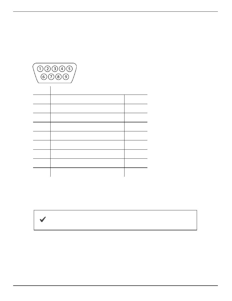
DB-9 Diagram
Pin
Signal Name
1
Carrier Detector
DCD
2
Receive Data
RXD
3
Transmit Data
TXD
4
Data Terminal Ready
DTR
5
Signal Ground/Common
GND
6
Data Set Ready
DSR
7
Request to Send
RTS
8
Clear to Send
CTS
9
Ring Indicator
RI
Communication Overview
The instrument can be programmed to use either Modbus or SDI-12. Modbus and SDI-
12 cannot be used at the same time. The protocol that is in use will block
communication of the other.
See the Aqua TROLL 400 Modbus and SDI-12 Reference Guide
for registers and programming information.
Prior to connecting the instrument to the controller, you must configure communication
settings using the Comm Kit Software and the Communication Device.