GW Instek GFC-8010H User Manual
Page 3
FREQUENCY COUNTER
USER MANUAL
3
3.PRECAUTIONS BEFORE OPERATION
3-1.Unpacking the Instrument
The instrument has been fully inspected and tested before shipping from
the factory. Upon receiving the instrument, please unpack and inspect it to
check if there is any damages caused during transportation. If any sign of
damage is found, notify the bearer and/or the dealer immediately.
3-2.Checking the Line Voltage
The instrument can be applied any kind of line voltage shown in the table
below. Please check the line voltage indicated in the label attached on the
real panel to replace correct fuses.
WARNING. To avoid electrical shock the power cord
protective grounding conductor must be connected to ground.
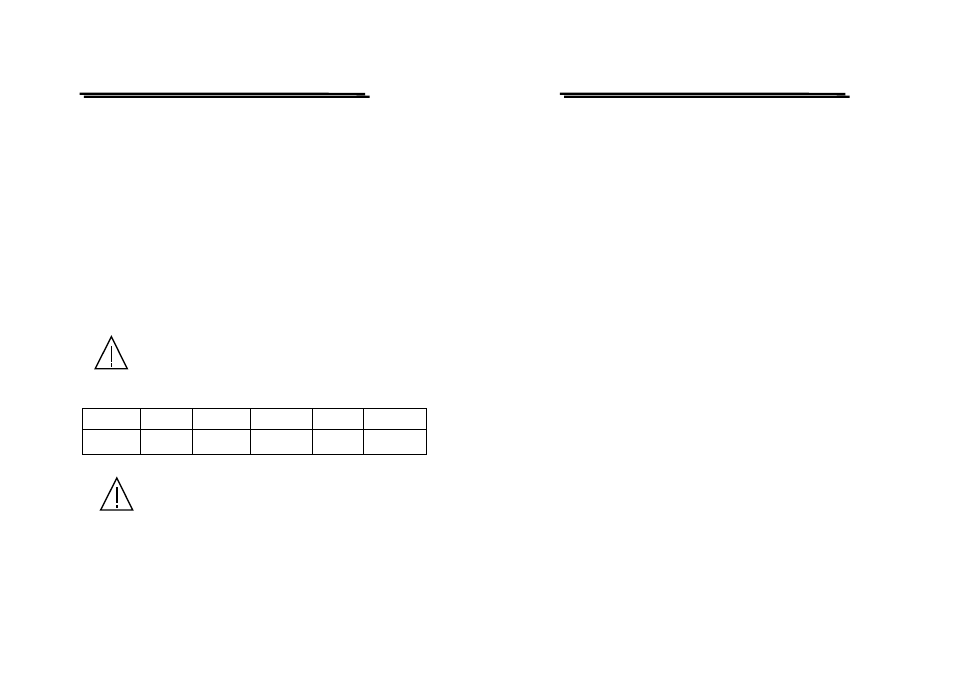
When line voltages are changed, replace the required fuses shown as below:
Line voltage
Range
Fuse
Line voltage
Range
Fuse
100V
120V
90-110V
108-132V
T160mA
250V
220V
230V
198-242V
207-253V
T100mA
250V
WARNING. To avoid personal injury, disconnect the power
cord before removing the fuse holder.
FREQUENCY COUNTER
USER MANUAL
4
3-3.Equipment Installation, and Operation
Ensure there is proper ventilation for the vents in the case. If this
equipment is used not according to the specification, the protection
provided by the equipment may be impaired.
3-4.General Preparation
1) When the impedance is 1MΩ, the maximum voltage applied to the input
depends on the frequency and the position of the SENSITIVITY switch.
This relationship is shown in Fig. 6, and the values given in this table
must be strictly observed. Initially set SENSITIVITY to 1/10, if the
counter doesn’t count, set the switch to 1/1 range and then perform
measurement. This procedure will reduce the danger of damaging the
input circuit.
2) Use an AC power source within 100V, 120V, 220V, or 230V±10%.
3) Use the instrument within an ambient temperature range of 0~40℃. Do
not put the counter on the top of high temperature equipment and be sure
not to block the ventilation of the instrument.
4) Never permit water to enter the interior of the instrument and never
subject the instrument to severe mechanical shock.
5) When the instrument is operated in an especial noisy environments, insert
a noise filter into the power source.
6) When low frequencies are measured, push the low pass filter switch can
attenuate high frequency components to prevent probable false triggering.