Fire-Lite LCD-80FC Remote Fire Indicator User Manual
Page 9
LCD-80FC Instruction Manual — P/N 53244:B 5/13/2013
9
SW1 DIP Switch Settings
The LCD-80FC Indicator
• One Indicator - if a single LCD-80FC is the only indicator connected to the EIA-485 loop,
Switch 3 must be set to the ON position to allow the FACP to supervise the indicator.
• Multiple Indicators - if multiple LCD-80FC indicators are connected to the EIA-485 loop,
the indicator physically connected as the last device on the loop (farthest from the ‘OUT’
terminals on the FACP) must have Switch 3 set to the ON position in order to supervise all
indicators on the loop. All remaining indicators must have Switch 3 set to the OFF position
for proper supervision and operation.
It is important to note that the function switches on all LCD-80FC indicators will operate regardless
of the setting of Switch 3.
A break (open circuit) in the power or EIA-485 connections creates an LCD-80FC Indicator fault at
the control panel. All indicators before the break will continue to display information (but the func-
tion switches on these LCD-80FCs will no longer operate).
4 through 6 = Configuration for use with a particular FACP.
Switches 4, 5 and 6 are used to select the FACP (Fire Alarm Control Panel) which is being con-
nected to the LCD-80FC. Refer to the following table for the appropriate switch settings.
7 and 8 = Future use.
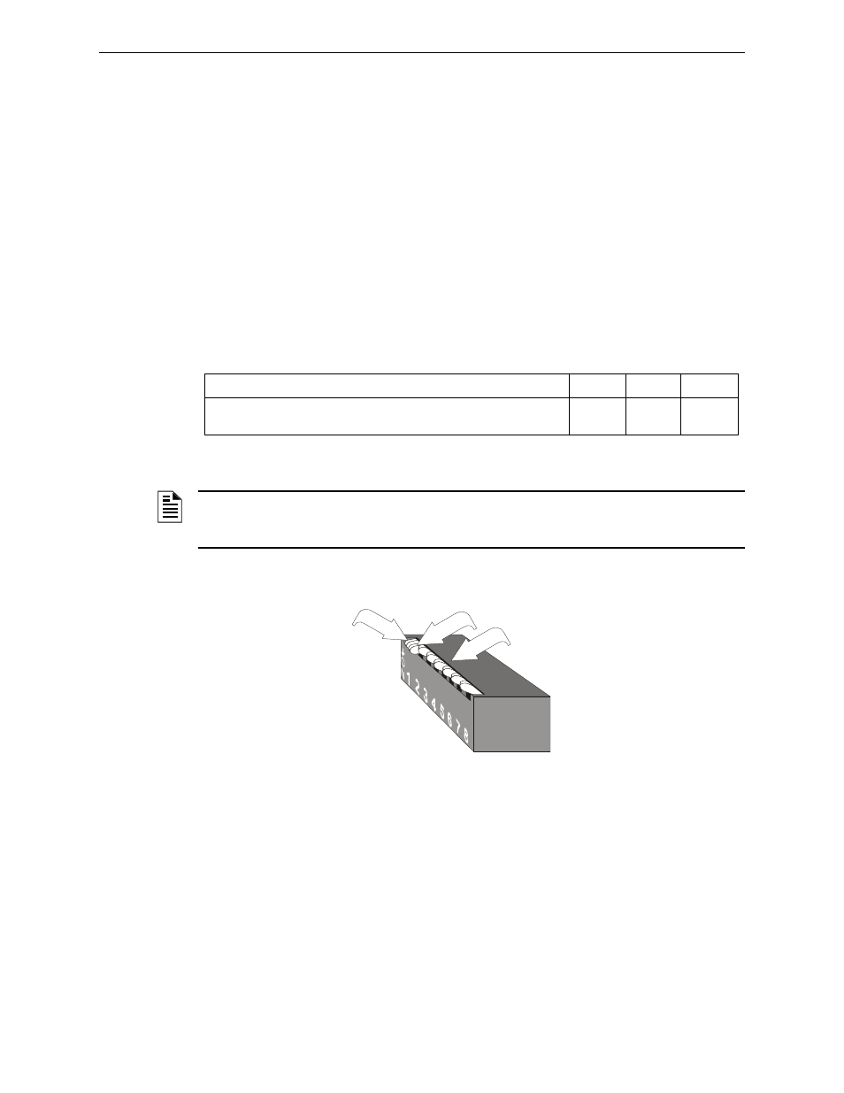
SW1 DIP switch settings as illustrated in Figure 2.2 are as follows:
1. DIP switch 1: ON = function buttons are enabled
2. DIP switch 2: ON = piezo sounder enabled
3. DIP switch 3: OFF = Receive Only. This setting is used for all indicators except the last or
only LCD-80FC Indicator on the EIA-485 line
4. DIP switches 4 through 6: OFF = Configured correctly for operation with the available
FACP (Refer to Table 2.1.)
5. DIP switches 7 and 8: OFF (these switches are not used)
Fire Alarm Control Panel
SW1-4
SW1-5
SW1-6
Use This Setting for:
MS-9200UDLS, MS-9600LS, MS-9200UD, and MS-9600
OFF
OFF
OFF
Table 2.1 Dip Switch Settings
NOTE: Depending on the FACP which is connected to the LCD-80FC, it may be necessary to
enable communication with the indicator in the FACP programming. Refer to the appropriate
FACP manual for programming information.
switch 1 shown
in ON position
switch 2 shown in ON position
d
ip
swflcd8
0d
c.wmf
switches 3 through 8
shown in OFF position
Figure 2.2 DIP Switch Settings Example