Section 4: electrical connections, 1 power connections, Specifications for the lcd-80fc – Fire-Lite LCD-80FC Remote Fire Indicator User Manual
Page 16: Power connections, Sections 4.1 and secti
16
LCD-80FC Instruction Manual — P/N 53244:B 5/13/2013
Section 4: Electrical Connections
4.1 Power Connections
The LCD-80FC Indicator can be powered by the FACP (refer to the specific technical manual for
the proper connection of the LCD-80FC) or from a remote UL listed, filtered power supply such as
the FCPS-24FS6/8C. The power run to the indicator must be power-limited but need not contain a
power supervision relay since loss of power is inherently supervised through loss of communica-
tion with the indicator. Maximum LCD-80FC current draw from the power supply (under normal
and alarm conditions) is 64.3 mA. Maximum current draw from the control panel's secondary
power source (batteries) under loss of AC power is 25 mA, since the LCD backlight is turned off
during AC loss. Backlighting is turned back on during AC loss only for alarm conditions in the
system. 12 - 18 AWG (0.75 - 3.25 mm
2
) wire for 24 VDC circuit is acceptable. Power wire dis-
tance limitation is set by 1.2 volt maximum line drop from source to end of circuit.
Specifications for the LCD-80FC
•
Operating Voltage Range: 18 VDC to 28 VDC
•
Current Consumption @ 24 VDC nominal (filtered and nonresettable):
•
Normal/Standby (no activity): 64.3 mA
•
Trouble Condition: 64.3 mA
•
Alarm: 64.3 mA
•
AC Fail (not backlit): 25 mA
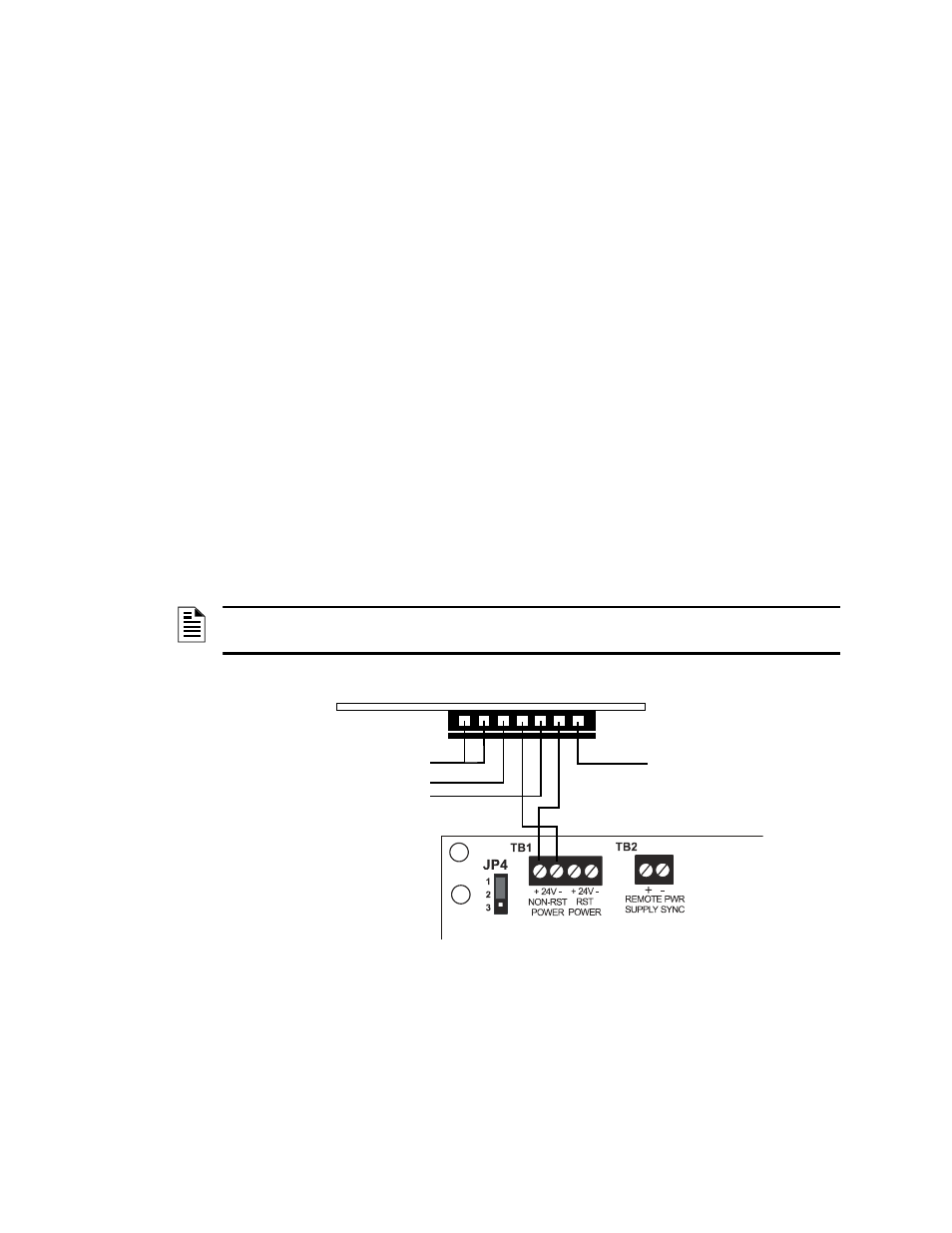
Refer to the illustrations on the following pages for power connections from the LCD-80FC to the
MS-9200UDLS, MS-9600LS, and FCPS-24FS6/8C
NOTE: These connections must be power-limited and the +24 VDC nominal power input must
be filtered and nonresettable.
P2
LCD-80FC
no connection
+24 VDC OUT
-24 VDC OUT
Earth Ground Option
- +
MS-9200UDLS
Figure 4.1 Power Wiring to the MS-9200UDLS