0 installation, 1 mounting, 2 power and i/o connections – Detcon 1640-N4X User Manual
Page 9: Installation, Mounting, Power and i/o connections, Figure 4 dimensional overview
1640-N4X
1640-N4X Instruction Manual
Rev. 0.0
Page 5 of 28
3.0 Installation
The Detcon Model 1640 s a wall-mount enclosure, and can be mounted anywhere that is rated safe for NEMA
4X enclosures. The enclosure is equipped with wall-mounting brackets for easy wall mount installations.
3.1 Mounting
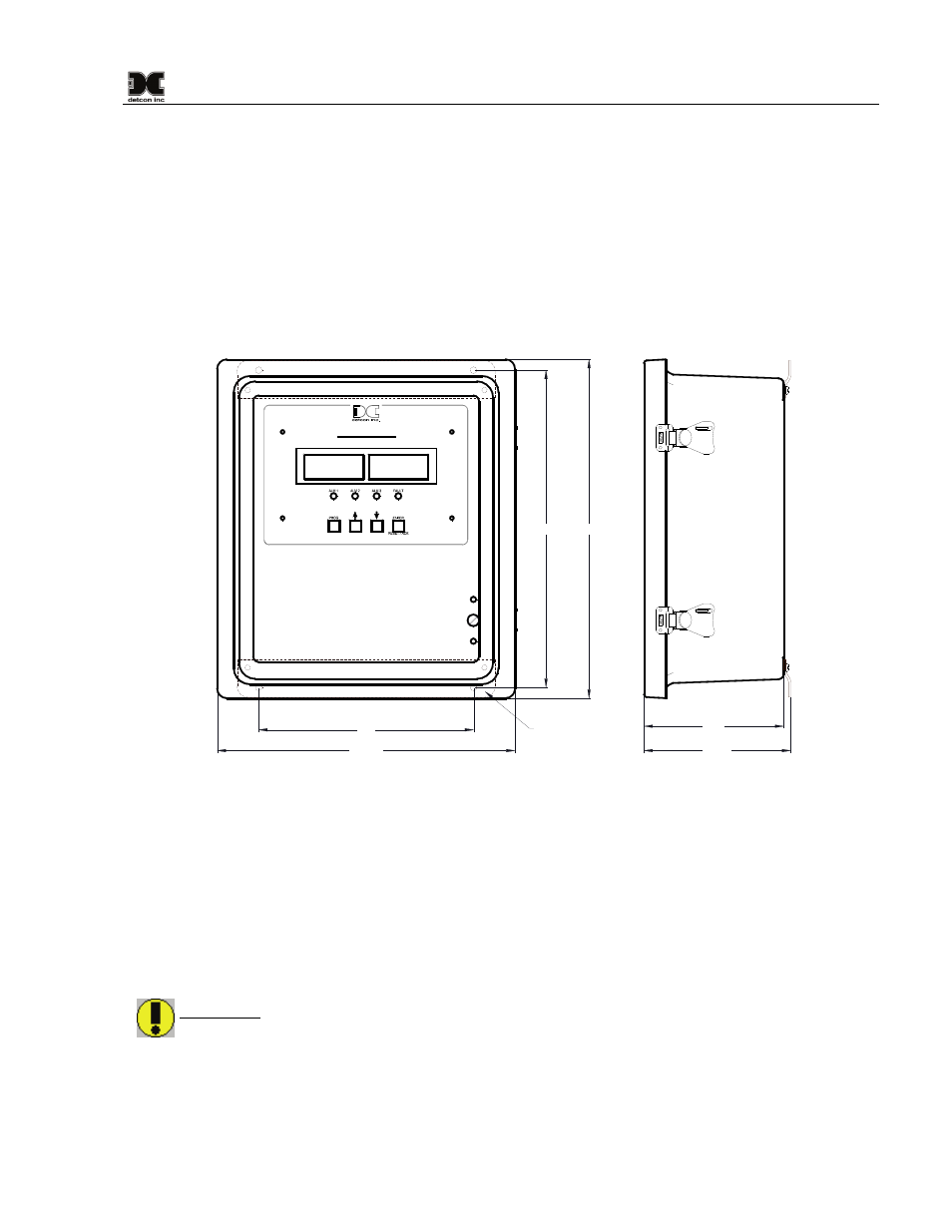
Securely mount the 1640 Enclosure in accordance with Figure 4.
NOTE: AC power should be kept separate from DC power and signals within conduit runs.
15.75"
14.75"
10"
13.85"
6.85"
Mounting Flanges
6.5"
Model 1640-N4X
Gas Detection / Alarm System
Figure 4 Dimensional Overview
3.2 Power and I/O Connections
Serial Connections
1. For Serial Units, connect the RS-485 Modbus™ network to the terminal blocks labeled “Primary RS-
485,” “A,” “B,” and “Shld” (Figure 5). Ensure that the network is properly laid out. Proper layout of
the RS-485 network is important for correct operation. Refer to Appendix A (RS-485 Integration and
Wiring) for proper network layouts.
WARNING: The use of the 24VDC output to power external components should be restricted to no
more than 4Amps maximum (96 Watts). This equates to about 32 sensors and/or field devices,
maximum. Care should be taken to insure that the total current of equipment utilizing this power does
not exceed the 4Amp rating, as this may cause detrimental damage to the unit and will void the
warranty.