Figure 5 typical rs-485 connections, Analog connections, Figure 6 installing i/o modules – Detcon 1640-N4X User Manual
Page 10
1640-N4X
1640-N4X Instruction Manual
Rev. 0.0
Page 6 of 28
Note: If there are no I/O Modules installed in the unit, J2 must be plugged into J1 for RS-485
Communication. If I/O Modules are installed in the unit J1 must be plugged into the left most module,
and J2 must be plugged into the right most module for RS-485 Communication.
A
B
+
RS-485 VDC
Primary Out
Figure 5 Typical RS-485 connections
Analog Connections
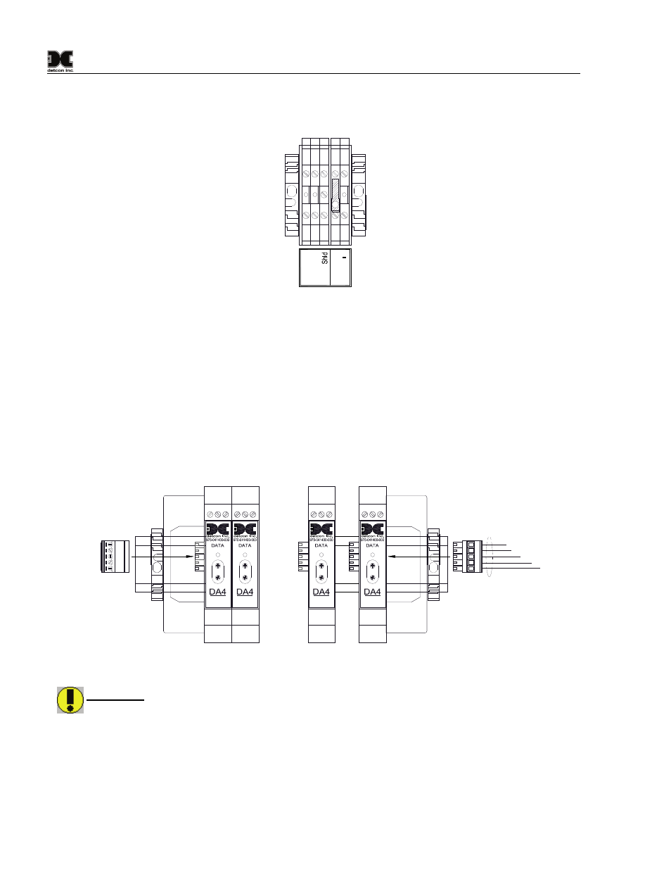
2. For Analog Sensors, communication is accomplished by using Detcon DA4 modules and the RS-485
Modbus™. The 4-20mA devices are connected directly to the DA4 modules, while the DA4 modules
are connected via the RS-485 Modbus™ to the 1640 (Figure 7). All DA4’s can be mounted within the
enclosure and should be mounted starting from the left moving the ME-Bus End Spacer next to the
Terminal Blocks, and adding modules to the right. Plug the Female Connector (J1) from the RS-485
Output Terminal Blocks onto the Left Most Module. Move the Din-Rail End Stop to the right as
modules are added. Plug the Male RS-485 and Power Connector (J2) into the last module added on
the right. The correct setup of the DA4’s is covered in Section 4.2.4 Setup Channel Data.
4-20mA
INPUT
COMM
M
S
D
L
S
D
SB
A
-
+
S
B
A
-
+
4-20mA
INPUT
COMM
M
S
D
L
S
D
RS-485 and Power Cable
RS-485
Cable to
Output Terminal
Blocks.
Add
Additional
Modules
ass
needed.
Maximum
of 12
Modules.
J1
J2
4-20mA
INPUT
COMM
M
S
D
L
S
D
4-20mA
INPUT
COMM
M
S
D
L
S
D
Figure 6 Installing I/O Modules
WARNING: The 24VDC used to power internal I/O Modules and attached devices is to be restricted
to no more than 4Amps maximum (96 Watts). This equates to approximately 8 DA4 Modules with 32
sensors and/or field devices attached. Care should be taken to insure that the total current of
equipment utilizing this power does not exceed this 4Amp rating, as this may cause detrimental
damage to the unit and will void the warranty.
Note: If there are no I/O Modules installed in the unit, J2 must be plugged into J1 for RS-485
Communication. If I/O Modules are installed in the unit J1 must be plugged into the left most module,
and J2 must be plugged into the right most module for RS-485 Communication.