0 setup, 1 front panel user interface, 2 main menu – Detcon 1640-N4X User Manual
Page 13: Setup, Front panel user interface, Main menu, Figure 9 front panel
1640-N4X
1640-N4X Instruction Manual
Rev. 0.0
Page 9 of 28
4.0 Setup
4.1 Front Panel User Interface
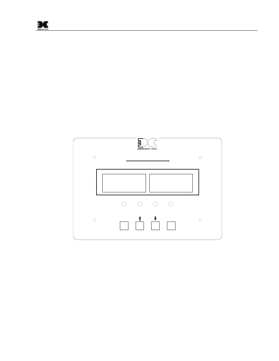
The Main Display is a backlit LCD that has 4 lines by 40 characters. In normal operation the channel’s
information will be displayed as “01> XXXX ppm GAS”. If any channel is in an alarm condition, “01>
XXXX IN ALARM ” will be displayed. If any channels are in Fault, they will display “01> XXXX IN
FAULT ”. Any channels are not communicating with the controller will be displayed as “01> XXXX
COMM ERROR ”. Fault and Alarm conditions are also displayed by the use of four (4) LED indicators on the
front panel. The LED’s are labeled ALARM 1 (yellow), ALARM 2 (amber), ALARM 3 (red) and FAULT
(blue).
The 1640 user interface consists of four function keys on the front panel. These keys are labeled: “PROG”,
“u” (Up Arrow), “v” (Down Arrow), and “ENTER”. The “ENTER” key doubles as a “RESET/ACK” key and
is labeled as such.
ALM1
ALM2
ALM3
FAULT
PROG
ENTER
RESET/ACK
Model 1640-N4X
Gas Detection / Alarm System
Figure 11 Front Panel
4.2 Main Menu
Unit Setup is accomplished by use of the Main Menu. Parameters for channel data, alarms, relays, and other
functions of the unit can be set via the Main Menu. The correct parameters must be entered into the unit
before the unit will operate properly. The Main Menu consists of 9 items:
SET # OF CHANNELS
SET COM1 BAUD RATE
SET COM2 BAUD RATE
SETUP CHANNEL DATA
SET CHANNEL ALARMS
SET RELAY FUNCTION
SET MODBUS ADDRESS
CALIBRATION MODE