2 analog sensors (4-20ma), Analog sensors (4-20ma), Figure 2 da4 4-20ma configuration – Detcon 1640-N4X User Manual
Page 6
1640-N4X
1640-N4X Instruction Manual
Rev. 0.0
Page 2 of 28
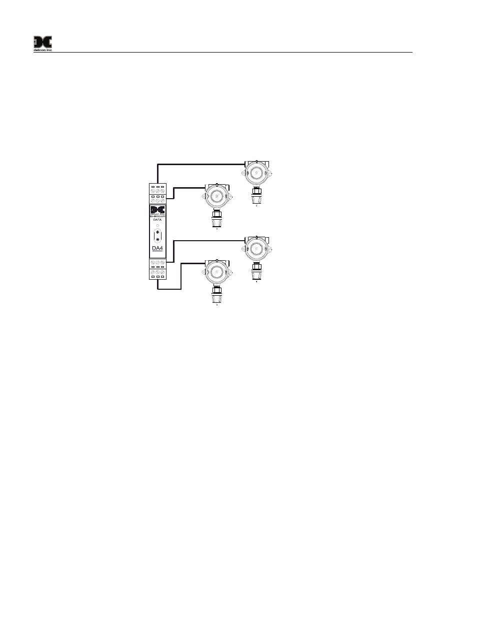
1.2 Analog Sensors (4-20mA)
Another method of integration is accomplished by using 4-20mA signal output devices with Detcon DA4
Modules (Figure 2). The DA4 Module receives a 4-20mA analog signal corresponding to the range of
detection then changes it to Modbus™ before relaying the information to the 1640 Controller. The Sensor’s
output signal is calibrated so that a 4mA input represents a reading of “0” and a 20mA input represents a
reading of full scale. The scale used for each sensor is user programmable and can be set in the field.
Readings outside the range of 4-20mA will cause a fault, and the unit will display “IN FAULT” for that
device.
4-20mA
INPUT
COMM
M
S
D
L
S
D
Typical Sensors
Sensor 2
Sensor 1
Sensor 3
Sensor 4
Figure 2 DA4 4-20mA Configuration
Analog 4-20mA networks are typically recognized as the most fail-safe approach. When using DA4
Module(s), the 1640 can communicate with up to 32 analog input channels. The enclosure can handle 8 DA4
Modules and associated sensors.