Figure 6 typical analog sensor wiring – Detcon 1640-N4X User Manual
Page 11
1640-N4X
1640-N4X Instruction Manual
Rev. 0.0
Page 7 of 28
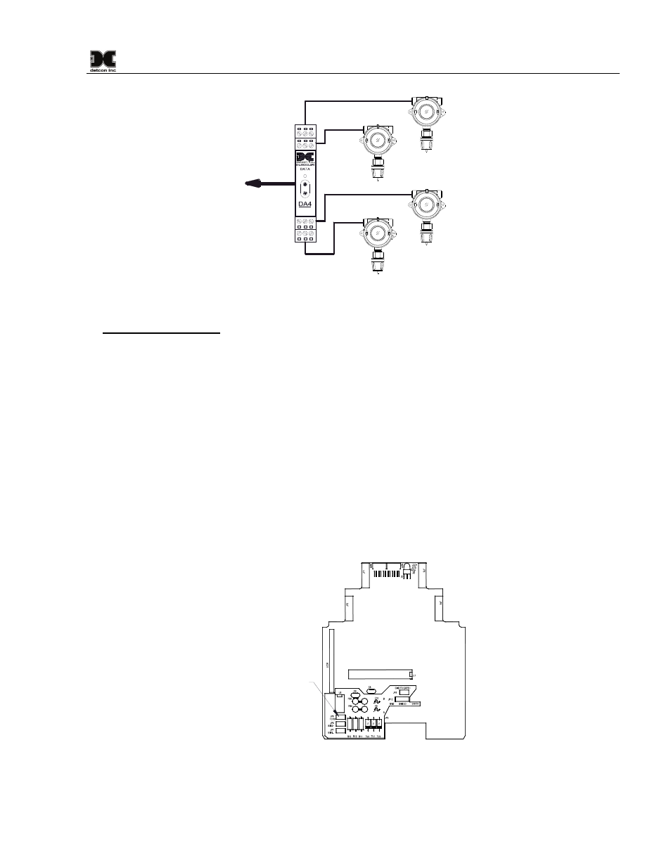
4-20mA
INPUT
COMM
M
S
D
L
S
D
Typical Sensors
RS-485 to 1640
Sensor 2
Sensor 1
Sensor 3
Sensor 4
Figure 7 Typical Analog Sensor Wiring
General Wiring Notes:
When I/O Modules are located at a remote distance from the controller, an end-of-line terminating resistor
is required to enhance communications reliability. Identify the last I/O Module in the loop, and open the
module casing using the clip release points. Locate and install the jumper on JP6 (TERM) Figure 8. This
adds a 120
Ω resistor to the end of the line. If applicable, add a 120Ω resistor to the last Modbus™ gas
sensor.
Follow generally accepted guidelines for RS-485 serial networks. Do not wire I/O Modules and/or
Modbus™ gas sensors in long-distance ‘T-Tap’ configurations. Stay with direct serial configurations. See
Appendix A for serial communications configuration guidelines.
Use Detcon Recommended cabling whenever possible.
• Belden P/N 1502P cable is recommended for a single cable providing serial communications and
power.
• Belden 9841 cable is recommended for a single cable providing serial communications only.
Ground the cable shielding at the Model 1600A-N4X Controller only. Other points of grounding may
cause a ground loop, and induce unwanted noise on the RS-485 line, which in turn may disrupt
communications.
Jumper located
on component
side of PCB
Figure 8 I/O Module Termination jumper (JP6)
3. Connect external annunciators to the relay terminals provided on the back of the 1640 Controller PCA.
The Alarm Relays are labeled “FAULT”, “ALM3” (Alarm 3), “ALM2” (Alarm 2), and “ALM1”