Figure 13 unbalanced data bus, Figure 14 data bus using two repeaters, Figure 15 repeater wiring diagram – Detcon 1640-N4X User Manual
Page 27
1640-N4X
1640-N4X Instruction Manual
Rev. 0.0
Page 23 of 28
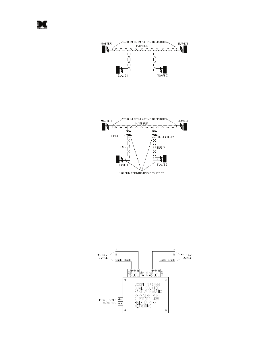
Figure 15 Unbalanced Data Bus
The addition of 2 repeaters (Figure 16) can solve this problem. The repeaters look like short stubs to the main
bus, and at the same time they create 2 new buses that have all the same characteristics as the main bus. Each
leg must have termination resistors to balance the new data bus.
Figure 16 Data Bus using two repeaters
Be sure to check the equipment being installed. Some manufacturers include a built-in terminating resistor
that can be selected by a jumper or dipswitch. Detcon Model 1640 has such a jumper located on the FA-isonet
card. The jumper is labeled “120 ohm Term.”
Detcon 600 series gas sensors and DA1 modules do not include this resistor, and therefore, if one of these
devices is the last on the RS-485 bus, a discrete 120 ohm resistor should be placed across the “A” and “B”
terminals on the connector board. Figure 17 illustrates the wiring scheme of a repeater when used in a wiring
bus with DA-1 devices.
Figure 17 Repeater wiring diagram