0 trouble-shooting, 1 sensor faults, 2 troubleshooting rs485 networks – Detcon 1640-N4X User Manual
Page 22: Trouble-shooting, Sensor faults, Troubleshooting rs485 networks
1640-N4X
1640-N4X Instruction Manual
Rev. 0.0
Page 18 of 28
6.0 Trouble-shooting
6.1 Sensor Faults
The unit is set up such that Sensor faults will set Fault alarms associated with that sensor. If a sensor goes into
a fault condition, that channel will flag a fault. From the “Main Screen” each channel can be quickly viewed
to see which channel is causing the fault. That sensor should be then checked to find the cause of the fault.
Faults are logged in the Alarm History for aid in tracing intermittent sensor problems. Refer to the appropriate
sensor manual for more information on trouble-shooting sensor faults.
6.2 Troubleshooting RS485 Networks
The first step in finding the bad device or several bad devices is to start at the master:
1. Disconnect the data cable bus wires going to all of the slave devices from the output terminal blocks
(A and B).
2. Connect a known working slave device directly to the master (attached directly to the output terminal
blocks) and make sure that it is functional. If it is not, replace the 1640 Controller PCA.
3. Disconnect the working device connected in Step 2, and re-connect the data cable bus wires (A&B) to
the master.
4. Use a voltmeter to measure the voltage across the A and B wires and write the reading down. This
reading should be 400-500mV.
5. Go to the first slave device. Re-connect or plug the device in and measure the voltage across A and B.
Write down the reading. The measurement taken should be 400 to 500mV. If the voltage is not
within the specified range, verify that all devices have been unplugged from the data bus.
6. Unplug the first device and proceed to the next slave device. Record the meter readings. Again the
reading should be 400-500mV. If the reading is not 400-500mV a wiring problem may exist, or the
transmitter may be non-operational.
7. Repeat the procedure with each slave device, recording the readings along the way. If any of the other
readings taken are above or below the first reading by more than 50mV that unit’s transmitter or the
module should be replaced.
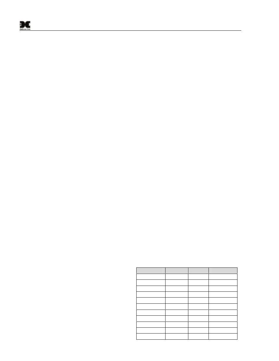
Slave
Master
MV
Difference
ID 01
425
451
26
ID 02
425
430
5
ID 03
425
486
61
ID 04
425
410
-15
ID 05
425
420
-5
ID 06
425
432
7
ID 07
425
422
-3
ID 08
425
415
10
ID 09
425
418
-7
ID 0A
425
440
15
ID 0B
425
310
115
Results similar to those
shown here should be
expected. In this example
slave device 03 and 0B
would need to be changed.