Figure 15 remote switch connections, Table 1 terminal board jumper settings – Detcon SW-HMI-32-N7 User Manual
Page 15
HMI Panel Instruction Manual
SmartWireless HMI Panel Instruction Manual
Rev. 1.0
Page 11 of 20
The wiring for the J7 connector is defined as follows,
PWR/GND: DC power connection from J2 of the terminal board. (11.5-30VDC)
A1/B1:
Primary Modbus
TM
connection (COMM1 Master) from J2 of the terminal board.
A2/B2:
Secondary Modbus
TM
connection (COMM2 Slave) to another remote display.
*Contact Detcon for wiring instructions when using the A2/B2 pin outs*
SW:
External switch connection for RESET/ACK function. (Normally Open)
The terminal board contains a set of jumpers that must be configured properly for the board to operate
properly. These jumpers are normally configured at the factory and should not be changed. Misplacement
of these jumpers may cause the wireless transceiver to become inoperative. The following table identifies
the jumper positions.
Table 1 Terminal Board Jumper Settings
Jumper Position
JP1 2-3
JP2 1-2
JP3 1-2
JP4 1-2
JP5 1-2
JP6 1-2
JP7 1-2
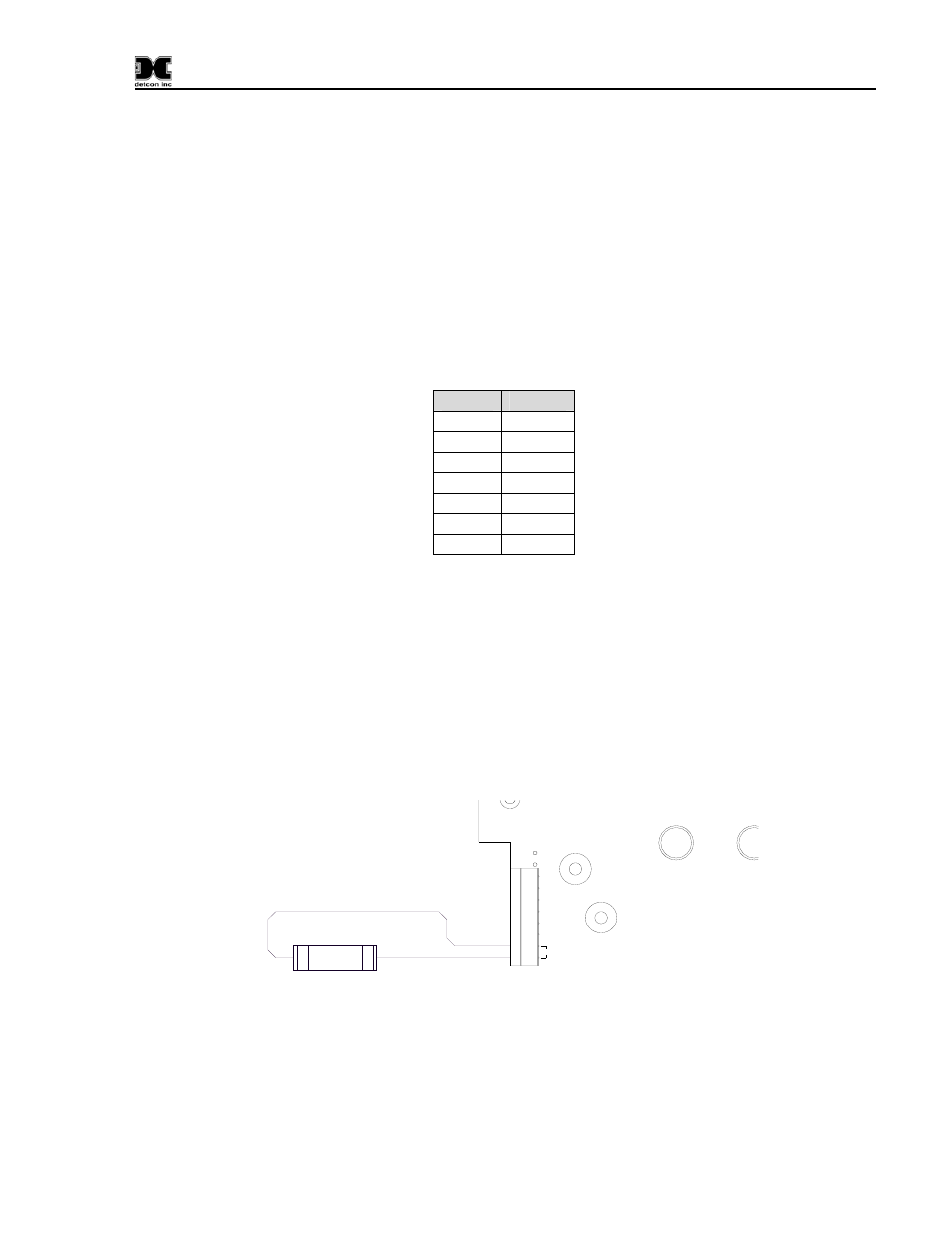
3.3 Optional Remote Alarm Reset/Acknowledge Switch (N7 Enclosure)
The Model SW-HMI-32-N4X panel display comes preinstalled with an external Remote Alarm
Reset/Acknowledge switch located on the side of the enclosure. The Model SW-HMI-32-N7 remote
display has the option of adding an external Remote Alarm Reset/Acknowledge switch. This enables the
user to reset or acknowledge alarms external from the SW HMI without having to open the enclosure. The
Reset Switch is a normally-open momentary contact push button type switch and will typically be mounted
on the bottom of the condulet which houses the Smart Battery pack for the N7 enclosure. Connect the
switch (SW1) to the terminals “SW” on connector J7 of the SW HMI PCA (See Figure 15). Once installed,
pushing the switch will execute the reset/acknowledge function.
RESET SWITCH
1
2
SW1
PWR
GND
A2
B2
A1
B1
SW
J7
D3
D4
Figure 15 Remote Switch Connections