Position terminal board rxt-300 transceiver – Detcon SW-HMI-32-N7 User Manual
Page 12
HMI Panel Instruction Manual
SmartWireless HMI Panel Instruction Manual
Rev. 1.0
Page 8 of 20
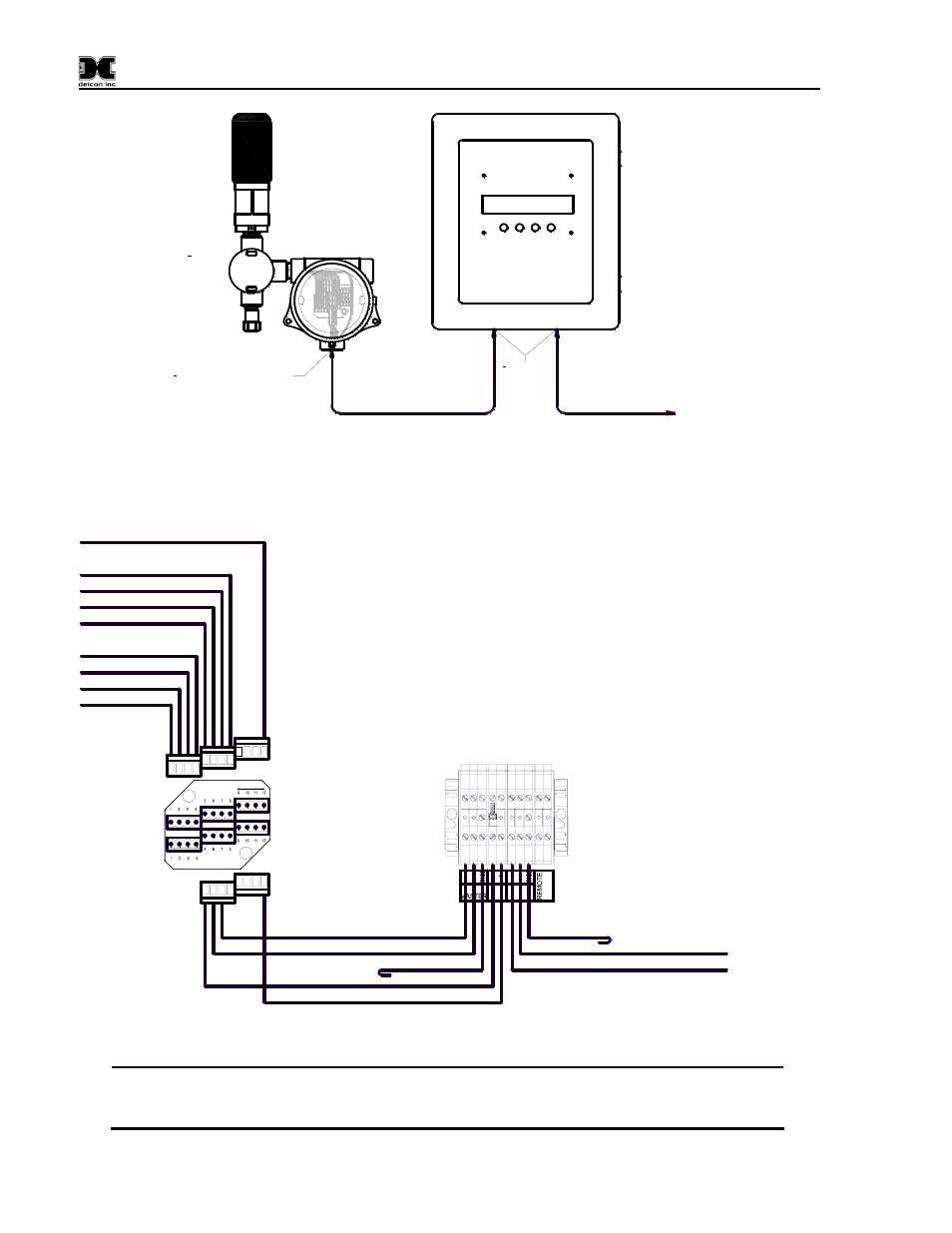
RXT-300 Wireless Transceiver
SW HMI to RXT-300
Modbus & Power Cable
Condulet w/
8-Position
Terminal Board
3
4
" NPT Cord Connector
(Cable Gland) Required
3
4
" NPT
T-Outlet
Box w/Drain
3
4
" NPT Cord
Connectors
(Cable Glands)
Required
SW HMI
SW HMI to
Secondary SW HMI
Modbus Cable
Secondary
SW HMI
RS-485
Master Port
Master Port
COMM1
Slave Port
COMM2
Figure 10 SW HMI N4X Enclosure w/RXT-300 & Secondary SW HMI Panel
Modbus & Power Cable
(Belden 1502P)
RS-485 VDC
Out
A
B
+
RS-485
SLAVE
A
B
R
E
SET
SW HMI
Terminal Block
Secondary
SW HMI
RS-485
Master Port
Blue (Modbus A)
White (Modbus B)
Drain Wire
Modbus Cable
(Belden 9841)
Black (Gnd -)
Red (Pwr +)
Drain Wire
White (Modbus B)
Blue (Modbus A)
Blue (Modbus A)
White (Modbus B)
Red (Pwr +)
White/Violet (Prog Reset)
White/Green (Prog Data)
White/Blue (Prog Clock)
White/Black (Serial Clock)
White/Brown (Serial Data)
Black (Gnd -)
8-Position
Terminal Board
RXT-300 Transceiver
4-Pin Phoenix
Connectors
4-Pin Phoenix
Connectors
Figure 11 RS-485 & Power Output Wiring for SW HMI N4X
NOTE: Ground the cable shielding (drain wire) at the SW HMI only. Other points of
grounding may cause a ground loop and induce unwanted noise on the RS-485 line which may
disrupt communications.