Warning, Caution – Star Water Systems Star 4in Sub Instr2&3-wire User Manual
Page 2
2
Copyright © 2014 Star Water Systems. All rights reserved.
3
Copyright © 2014 Star Water Systems. All rights reserved.
WARNING
ELECTRICAL SHOCk ALERT
Follow all local electrical and safety codes, as well
as the National Electrical Code (NEC) and the
Occupational Safety and Health Act (OSHA).
ELECTRICAL SHOCk ALERT
All electrical wiring or service should be done by a
qualified electrician.
EXPLOSION ALERT
Do not use to pump flammable or explosive fluids
such as gasoline, fuel oil, kerosene, etc. Do not use in
flammable and/or explosive atmospheres.
HAZARDOUS PRESSURE ALERT
Install pressure relief valve in discharge pipe. Release
all pressure on system before working on any
component.
CAUTION
ELECTRICAL SHOCk MAY OCCUR
Wire motor for correct voltage. See Electrical section
and motor nameplate.
ELECTRICAL SHOCk MAY OCCUR
Ground motor and controls before connecting to
power supply.
ELECTRICAL SHOCk MAY OCCUR
Follow wiring instructions in this manual when
connecting to power lines.
ELECTRICAL SHOCk MAY OCCUR
Protect power cable from nicks or cuts from sharp
objects or scraping on well casing when lowering
pump into well. Do not allow it to come into contact
with oil, grease, hot surfaces or chemicals.
ELECTRICAL SHOCk MAY OCCUR
The motor voltage and phase indicated on the motor
nameplate should be checked against the actual
electrical supply. Check your power source. Check
electrical supply for correct fusing, wire size, and
adequate grounding and transformer size.
PRODUCT DAMAGE MAY OCCUR
The power supply for a submersible pump should be
a separate circuit, independent of all other circuits. It
must be equipped with a fuse box of ample capacity.
PRODUCT DAMAGE MAY OCCUR
Shut off power source when voltage drops 10%
below rated voltage of motor.
FIRE SAFETY
For fire protection, power supply should be free
of any building, preferably on a direct line from
transformer. In event of fire, wires will not be
destroyed and water supply not cut-off.
NOTE: Install all electrical equipment in protected area to provide adequate ventilation for pressure switch
and controls to prevent moisture damage to components.
NOTE: Install pump, pressure tank, pitless adaptor or well seal in accordance with state and local plumbing
codes.
SAFETY INFORMATION
PREPARATION
Before beginning installation of product, make
sure all parts are present. Compare parts with
package contents drawing. If any part is missing or
damaged, do not attempt to assemble the product.
Contact customer service for replacement parts.
Estimated Installation Time: 2 hours.
Tools Required for Installation: Hacksaw,
screwdriver, pliers, pipe vise, pipe wrenches (2),
wire cutters, wire strippers/crimpers, adjustable
wrench (medium-large), Ohmmeter, propane torch,
knife or round file, small weight.
Materials Required for Installation: Control
box for 3-wire plus ground models (see chart on
page 6) Submersible pump cable, power cable,
pressure tank, shrink tube & butt connectors, 1-1/4
in. check valve, torque arrestor, hose clamps, pipe
fittings, pitless adaptor or well seal, pressure switch,
pressure gauge, pressure relief valve, tank cross,
1/4 in. minimum safety rope, electrical tape,. You
will also need either enough 1-1/4 in. Schedule 80
PVC pipe to reach 20 ft. below the static level or 20
ft. below the drawdown level of your well, or coiled
poly pipe rated for 160 PSI. Poly pipe cannot be used
for installations any deeper than 200 ft.
Optional Materials: 1-1/4 in. male barbed
adaptor for use with poly pipe, cable guards to
protect wire inside the well, thread tape and thread
paste.
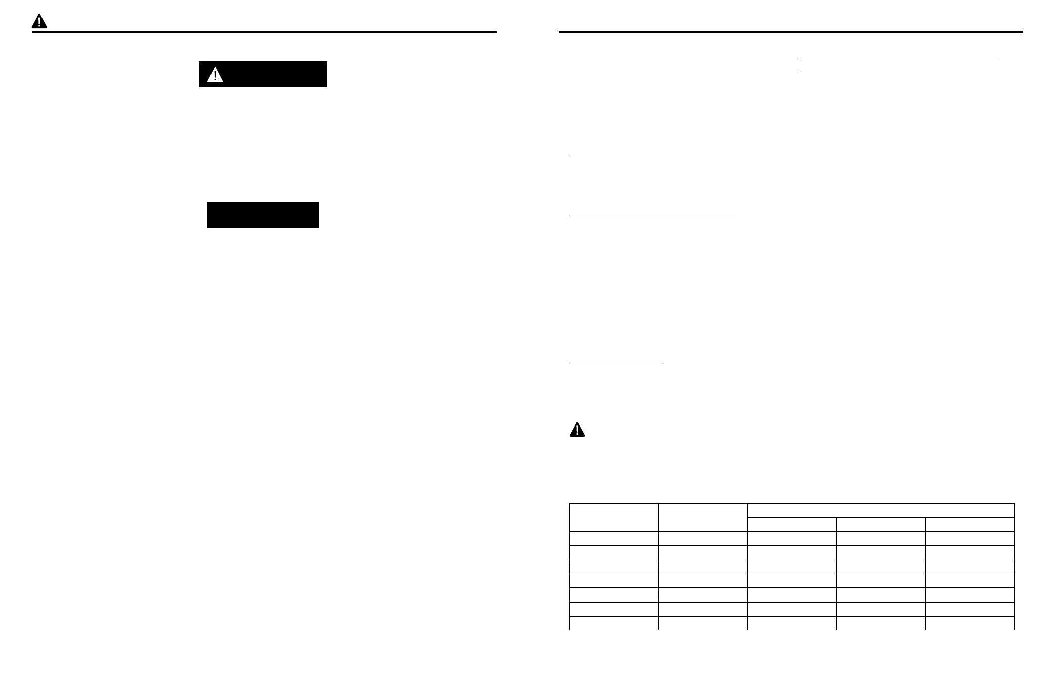
SUBMERSIBLE PUMP CABLE AND POWER
CABLE SELECTION
Check cable size against Submersible Wire Size Chart
A . For 3-wire plus ground models, motor and control
box voltage must match. Submersible power cable
must be UL listed for submersible pump applications.
For Canadian installations, type RWU, TWU, SGOW or
SWOW power supply cable is recommended. Cable
is selected for the maximum pump setting plus the
offset distance to the service entrance.
IMPORTANT: Use of wire sizes smaller than those
specified in the chart will cause low starting voltage,
may cause early pump failure and will void the
warranty. Larger wire sizes may always be used for
better economy of operation. Be sure voltage at
pressure switch or fuse is between the following
limits:
115V Rated - Between 104 & 127 volts
230V Rated - Between 210 & 250 volts
NOTE: A small AWG number, i.e. 10 Ga., is larger in
diameter than a large AWG number, i.e. 14 Ga.
The National Electric Code (NEC 250-43) requires a
separate ground wire be run down the well to the
submersible pump and connected to all exposed
metal parts of the pump and motor. Refer to the
most recent National Electric Code (NEC) Article 250
(grounding) for additional information.
NOTE: All wiring should be done by a qualified
electrician.
HP
Volt
Maximum Cable Length In Feet Using AWG Cable*
#14
#12
#10
1/2
110/115
100
160
250
1/2
230
400
650
1020
3/4
230
300
480
760
1
230
250
400
630
1-1/2
230
190
310
480
2
230
150
250
390
3
230
120
190
300
*
NOTE: Wire length is the total distance from power source to pump depth.
Wire Size Chart A
WARNING: 3-WIRE SUBMERSIBLES ONLY: This submersible pump must be wired
directly to a control box of the same horsepower and voltage rating in order to work
properly. IT MUST BE USED WITH WITH A CONTROL BOX.