Step 5 final assembly, Step 6 initial testing of drain basin system, Figure 5.1 – Star Water Systems S1104 User Manual
Page 6
6
© Copyright 2004. All rights reserved.
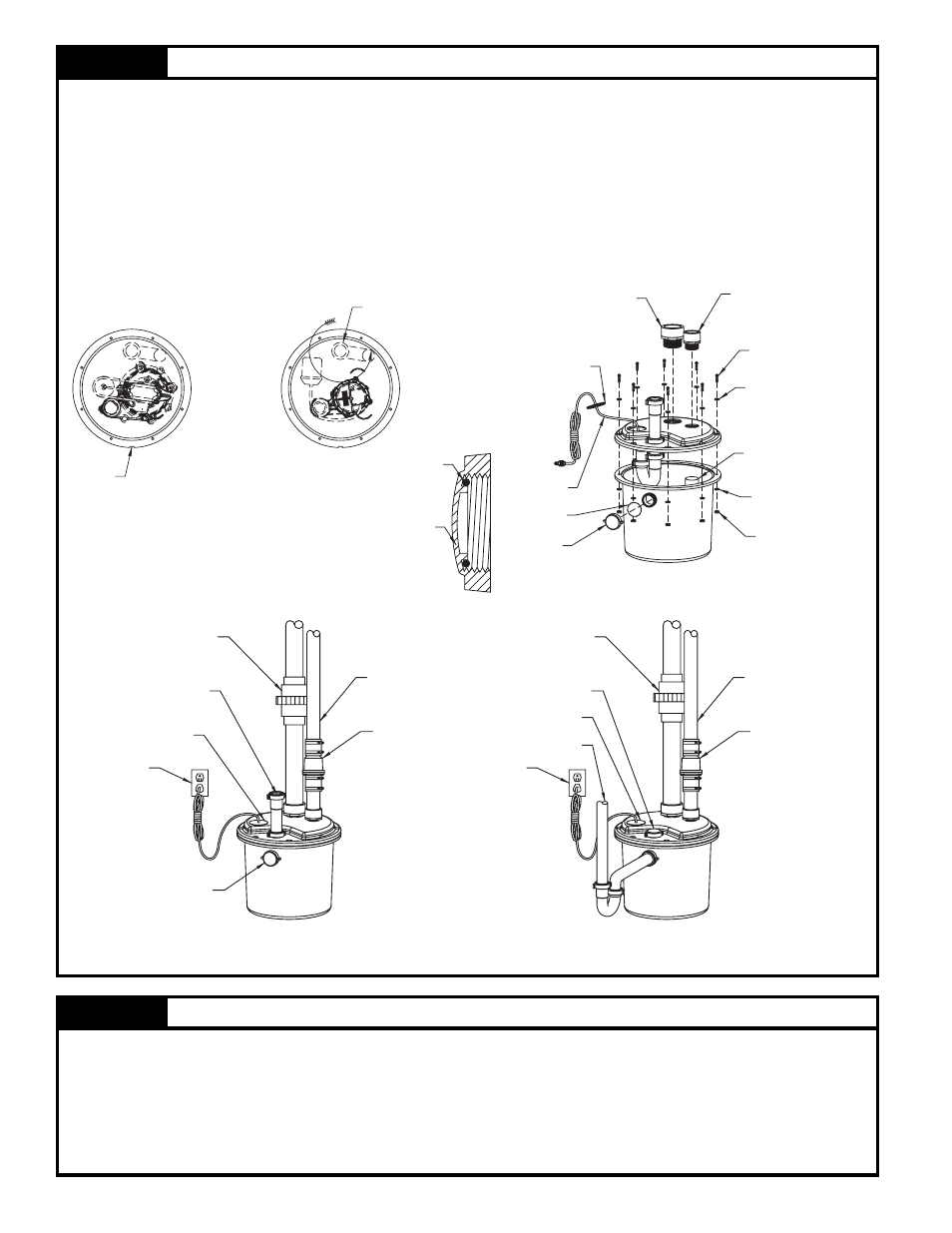
STEP
5
Final Assembly
NOTE: External plumbing confi guration will vary depending on the location of basin, location of main stack
and available space.
5.1) Place the pump in the basin as shown in Figure 5.1.
NOTE: If installing the internal trap, rotate the tail pipe to the orientation shown in Figure 5.1.
5.2) Install the lid components as shown in Figure 5.2.
NOTE: Pull excess cordage through the opening and install the cordseal as shown in Figure 5.3A.
Ensure o-ring is in the cap before installation.
5.3) Place the basin assembly in its fi nal position and complete plumbing. Secure all connections
(shown in 5.3A or 5.3B).
Figure 5.1
Figure 5.2
Figure 5.3A
Figure 5.3B
SK2005
SK2007A
SK2006
SK2006
SK2007B
*
*
CHECK VALVE MUST BE
PURCHASED SEPARATELY
*
STEP
6
Initial Testing of Drain Basin System
6.1) Plug the cord into a properly grounded GFCI receptacle.
6.2) Fill tank with water.
6.3) Check all plumbing for leaks as the basin fi lls.
6.4) Verify that the pump starts and stops.
6.5.) Check the discharge line for leaks as the pump empties the basin.
6.6.) Repeat steps 6.2 to 6.5 as necessary to insure proper operation.
6.7.) If problems persist refer to the troubleshooting guide located at the back of the manual.
1/4 - 20 x 1"
S.S. SCREWS
1/4 - 20 STD.
S.S. FLAT WASHERS
DISCHARGE PIPE
1 1/2" SLP x NPT
2" SLP x NPT
CORD SEAL
1/4 - 20
S.S. NUTS
1/4 - 20 STD.
S.S. FLAT WASHERS
(TORQUE TO 30 IN-LB)
SEE NOTE
(APPLY SEALANT TO THREADS)
CAP
O-RING
O-RING
CAP
CAP SECTION VIEW
KEY
TRAP INLET
GFCI
OUTLET
GFCI
OUTLET
CORD SEAL
CAP
UNION
(PURCHASED SEPARATELY)
CHECK VALVE
DISCHARGE PIPE
DISCHARGE PIPE
CHECK VALVE
CAP
UNION
(PURCHASED SEPARATELY)
CORD SEAL
INLET
INLET
INTERNAL TRAP INSTALLATION
STANDARD INSTALLATION