LumaSense Technologies INNOVA 1303 User Manual
Page 11
Chapter 1
________________________________________________________________________
_______________________________________________________________________
BE1085-14
1303 Multipoint Sampler and Doser
LumaSense Technologies A/S
Page 11 of 60
is lit, it indicates that the corresponding sampling valve
is open, see
section 3.5
. The 3 Way Valve to Analyz-
er/Waste Air lamps indicate which way the internal 3
way valve is set, see
section 3.5
.
Temperature Sensors Input:
6 inputs suitable for use with the INNOVA Air
Temperature Transducer Type MM0034 or Operative
Temperature Transducer MM0060.
Interface:
3 lamps which indicate the function of the IEEE inter-
face. If the Listen lamp is lit, the 1303 is receiving in-
structions or data from the system controller. If the Talk
lamp is lit, the 1303 is outputting data. If the SRQ lamp
is lit, the 1303 has generated a Service Request, see
section 4.1.1
and
4.2.6
. Full details of the IEEE Interface
are given in
Chapter 4
.
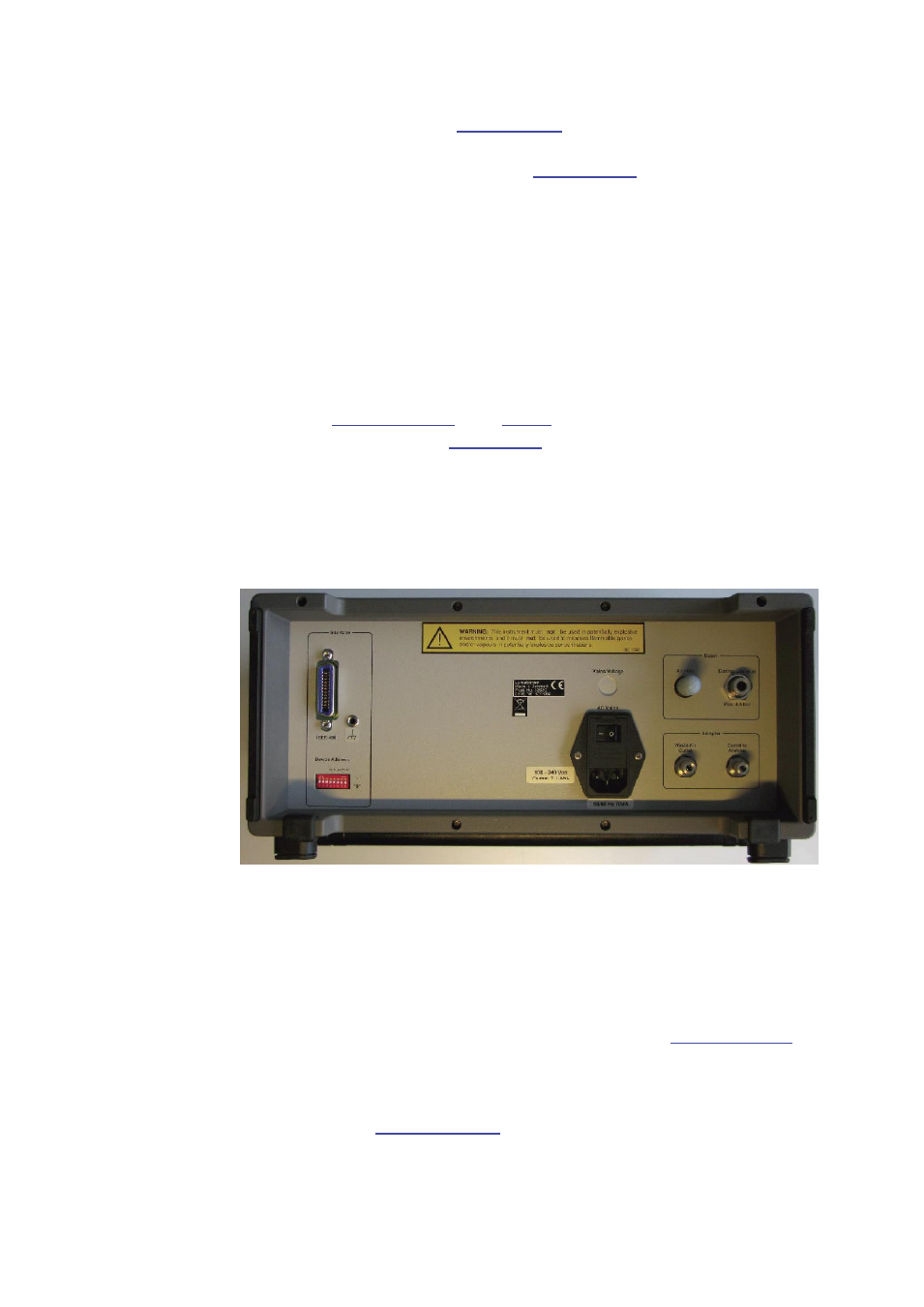
1.1.4
Rear Panel
Fig.1.3 The rear panel of the 1303
AC Mains:
A 3-pin connector accepting Power Cable for connection
to a single phase AC mains supply with protective Earth.
Mains Voltage:
Connect 1303 to mains supply with 100-240 Vac, 50/60
Hz
Dosing Gas Inlet:
Mounting stub for connection of a tracer-gas supply to
the 1303 using tubing AF0008. See
section 2.3.3
.
Outlet to Analyzer:
Mounting stub for connecting the sampler system of the
1303 to the inlet of an INNOVA Gas Monitor via tubing.
See
section 2.3.4
. Usable models are Type 1302, 1312
or 1412. In the following referred to as “Gas Monitor”.