3 connection to rs485, 4 connection schematic for analyzing devices – LumaSense Technologies ISR 6 Advanced User Manual
Page 17
ISR 6 Advanced Manual
Controls and Installation · 17
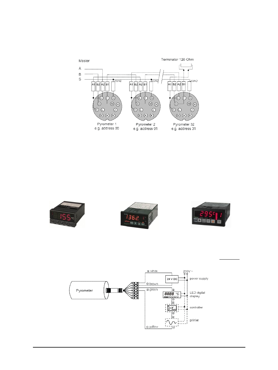
3.1.3 Connection to RS485
Half-duplex mode: A1 and A2 as well as B1 and B2 are bridged in the 12-pin round connector of
the connecting cable, to prevent reflections due to long stubs.
RS485 Bus System
It also safeguards against the interruption of the RS485 Bus System should a connecting plug be
pulled out. The master labels mark the connections on the RS485 converter. The transmission
rate of the serial interface in Baud (Bd) is dependent on the length of the cable. Values between
1200 and 115200 Bd may be set.
3.1.4 Connection schematic for analyzing devices
For temperature indication of the pyrometer, LumaSense offers pure indicators (series DA 4000).
LumaSense also offers indicators with features to change pyrometer parameters (DA 6000 and
DA 6000-N) as well as a fast digital PID controller PI 6000.
Digital Display
Parameterizing Indicator
Digital Controller
Additional analyzing instruments, including LED digital displays only need to be connected to a
power supply and the analog outputs of the pyrometer (exception: the digital display DA 6000
can also be connected with its serial interface, whereas the digital display DA 6000-N has to be
connected with its serial interface).
Connection Schematic for Analyzing Devices