LT Security LTD2516HE User Manual
Page 20
Digital Video Recorder User Manual version 1.0
20
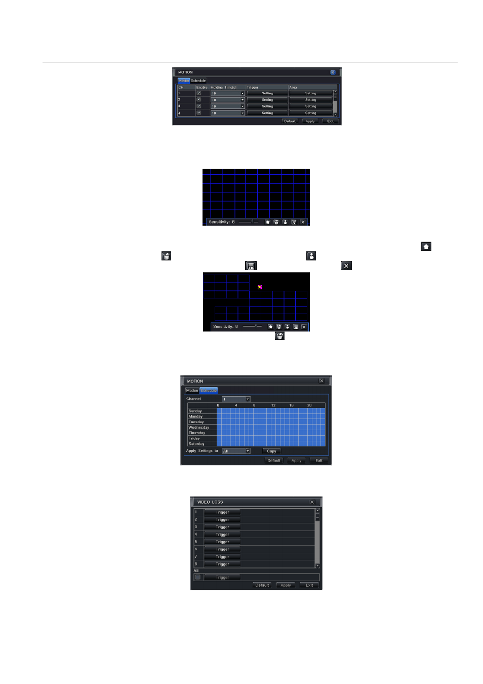
Fig 4-23 alarm configuration-motion
Step2: enable motion alarm, set alarm hold time which means time interval between two adjacent detective motions. If there is other motion detected
during the interval period which is considered continuous movement; otherwise, it will be considered that those two adjacent detective motions are two
different motion events. Click Trigger button, a dialog box will pop-up:
Step3: the setup steps of motion trigger are familiar with alarm handling; user can refer to Chapter 4.5.1 Sensor
alarm handling for more details.
Step4: click Area button, a dialog box will pop-up as Fig 4-24:
Fig 4-24 motion-area
Step5: in the Area interface, user can drag slide bar to set the sensitivity value (1-8), the default value is 4. The higher the value is the higher sensitivity you
get. Due to the sensitivity is influenced by color and time (day or night), user can adjust its value according to the practical conditions; click
icon, set
the whole area as detection area; click
icon, the set detection area will be cleared; click
icon, user can test whether the sensitivity value and
motion area are suitable accordingly
(refer to following picture); Click
icon, to save the setting; click
icon, exit current interface.
Note: when user drag mouse to set motion detection area, they have to click
icon to clear all set detection area firstly, and then make the
operation.
Step6: user can setup all channels with same parameters, tick off “all”, then to do relevant setup.
Step7: click “default” button to resort default setting; click “apply” button to save the setting; click “exit” button to exit current interface.
Schedule
Step1: enter into system configuration
alarm configuration
schedule; refer to Fig 4-25:
Fig3-25 alarm configuration-schedule
Step2: the setup steps of alarm schedule are familiar with schedule; user can refer to 4.4.1 Schedule for details.
4.5.3 Video loss
Step1: enter into system configuration
alarm configuration
video loss; refer to Fig 4-26:
Fig 4-26 alarm configuration-video loss
Step2: the setup steps of video loss trigger are familiar with alarm handling; user can refer to Chapter 4.5.1 Sensor
alarm handling for more details.
Step3: user can setup all channels with same parameters, tick off “all”, then to do relevant setup.
Step4: click “default” button to resort default setting; click “apply” button to save the setting; click “exit” button to exit current interface.