Figure 6, Switch installation (cable-end), Switch wiring – Hired-Hand PowerTrak: Auxiliary Status Switch Kit User Manual
Page 3
HIRED-HAND MFG., INC.
• 1733 Co Rd 68 • Bremen, Alabama 35033 • Phone 256-287-1000 • Fax 256-287-2000
Manual Part No. 4801-5320 rev 3-04 Page
3 of 6
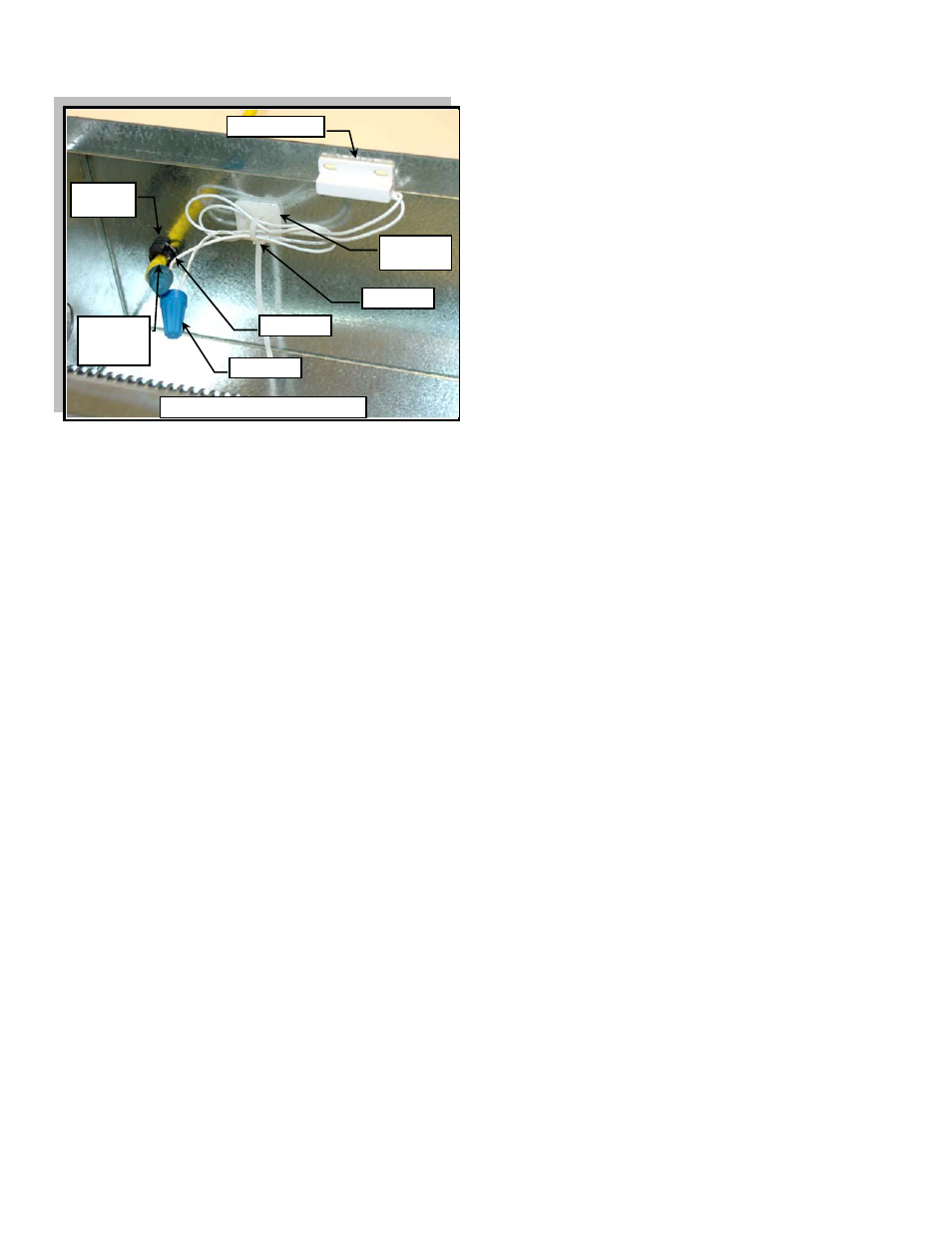
Grommet
Reed Switch
Cable
(Customer
Supplied)
1/2” Hole
Size
Cable-End Reed Switch
Cable Tie
Mount
Cable Tie
Wire Nut
FIGURE 6
SWITCH INSTALLATION (Cable-End)
6. Run the machine load block to the maximum set
cable-end position for status switch activation.
7. Use alcohol to clean the cabinet flange surface
where the reed switch will be applied. Ensure the
surface is completely clean and dry before
proceeding to the next step.
8. Line-up the reed switch with the magnet and attach
the reed switch to the center of the cabinet flange.
Refer to Figure 6.
9. Drill a ½” hole in the cabinet near the cable-end reed
switch.
10. Insert the supplied grommet and customer supplied
cable through the ½” hole.
SWITCH WIRING
NOTE: Prior to wiring the status switches to the
controller, determine the correct intended use of
the cable-end reed switch and the motor-end
reed switch. One of these switches will be used
to indicate when the curtain/vent is closed; The
other switch will be used to indicate when the
curtain/vent is open. Which reed switch is
labeled as “closed” or “open” will depend on the
specific application setup of the curtain or vent
to the PowerTrak™ Jr. Ensure that the wiring
from the reed switches (motor-end switch and
cable-end switch) to the controller is wired
accordingly.
11. Using the wire nut connectors, wire the cable-end
reed switches to the customer supplied cable. Refer
to Figure 10 for wiring the auxiliary switches to an
Evolution 3000 / 3001. Using a cable tie and cable
tie mount, secure the excess wire to the side of the
cabinet.
12. Wire the motor-end reed switch to customer supplied
cable with the wire nut connectors. The motor-end
wiring should be inserted through one of the cabinet
knock-outs beneath the motor. Secure excess wire.
CAUTION: Ensure that all wires and cable are secured
and placed so that they do not interfere or
become tangled with the load block, drive, or
motor during complete operation of the
PowerTrak™ Jr.
13. Test and ensure that the PowerTrak™ Jr., controller,
and curtains are operating correctly.