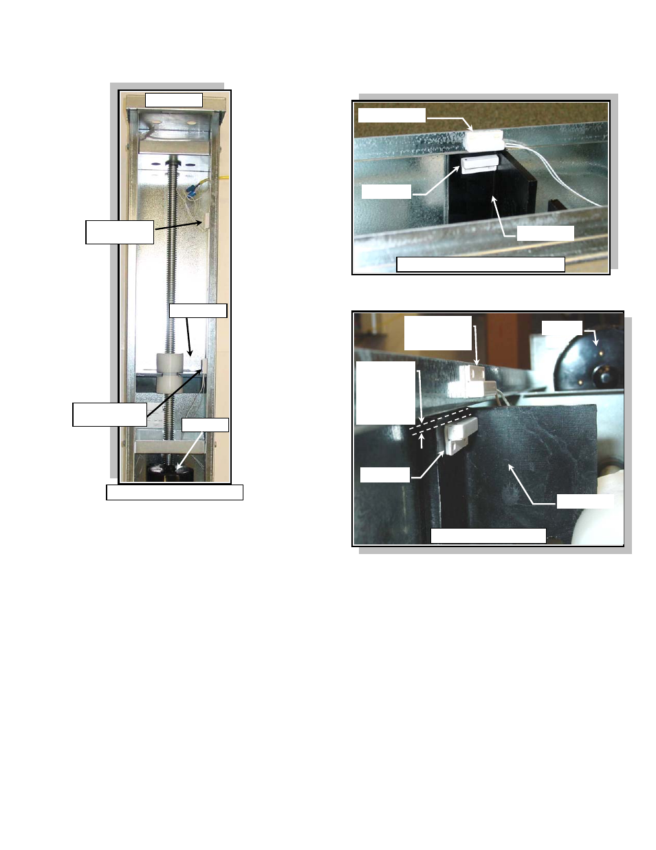
Figure 3, Kit components, Magnet installation – Hired-Hand PowerTrak: Auxiliary Status Switch Kit User Manual
Page 2: Figure 4, Figure 5, Switch installation (motor-end)
HIRED-HAND MFG., INC.
• 1733 Co Rd 68 • Bremen, Alabama 35033 • Phone 256-287-1000 • Fax 256-287-2000
Manual Part No. 4801-5320 rev 3-04 Page
2 of 6
Load Block
Magnet
Reed Switch
centered on the
cabinet flange.
Place the
Magnet
approx. 1/8”
off the edge of
the Load
Block.
Motor
Magnet Clearance
Status Switch
(Motor End)
Status Switch
(Cable End)
Load Block
Motor
Cable End
Auxiliary Switch Locations
Load Block
Magnet
Reed Switch
Magnet Mounted on Load Block
I. Mounting Auxiliary Status Switches to PowerTrak™ Jr.
FIGURE 3
KIT COMPONENTS
The PowerTrak™ Jr. Auxiliary Status Switch Kit contains
the items listed on Page 1 in the required parts table
except the insulated cable. The insulated cable is
customer supplied.
MAGNET INSTALLATION
The magnet is similar in appearance to the reed
switches except the magnet does not have attached
wires.
1. Use alcohol to clean the load block surface where
the magnet will be applied. Ensure the surface is
completely clean and dry before proceeding to the
next step. Refer to Figures 3, 4, and 5.
2. Allow 1/8” clearance from the edge of the load block
and attach the magnet to the load block using the
adhesive tape. The magnet should be located on
the load block side facing away from the motor.
Refer to Figure 5.
FIGURE 4
FIGURE 5
SWITCH INSTALLATION (Motor-End)
3. Run the machine load block to the maximum set
motor-end position for status switch activation.
4. Use alcohol to clean the cabinet flange surface
where the reed switch will be applied. Ensure the
surface is completely clean and dry before
proceeding to the next step. Refer to Figures 3, 4,
and 5.
5. Line-up the reed switch with the magnet and attach
the reed switch to the center of the cabinet flange.
The wires of the reed switch should be routed
toward the motor end. Refer to Figures 4 and 5.